Download
1 / 7
70 likes | 167 Views
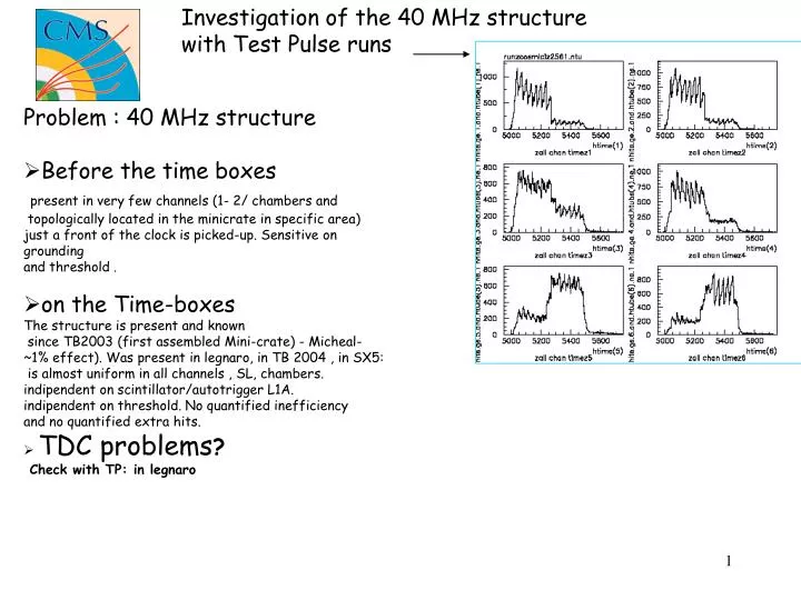
Investigation of the 40 MHz structure with Test Pulse runs. Problem : 40 MHz structure Before the time boxes present in very few channels (1- 2/ chambers and topologically located in the minicrate in specific area) just a front of the clock is picked-up. Sensitive on grounding

E N D
Investigation of the 40 MHz structure • with Test Pulse runs • Problem : 40 MHz structure • Before the time boxes present in very few channels (1- 2/ chambers and topologically located in the minicrate in specific area) just a front of the clock is picked-up. Sensitive on grounding and threshold . • on the Time-boxes The structure is present and known since TB2003 (first assembled Mini-crate) - Micheal- ~1% effect). Was present in legnaro, in TB 2004 , in SX5: is almost uniform in all channels , SL, chambers. indipendent on scintillator/autotrigger L1A. indipendent on threshold. No quantified inefficiency and no quantified extra hits. • TDC problems? Check with TP: in legnaro
TP_go on.. Or Orbitsignl L1A signal SC/Global Clock in CH1 TP in CH1 TDC fine countsin CH1 TDC windowin CH1 L1A signal inside CH1 LT trigger cotputby CH1, bx =i TP signals : flow of command with TP In the tests, TP was generated within 0 ns between staggered cell i.e emulates normal tracks in the middle of each semi-cell . Only cells in one semi-column per TRB were pulsed ( cell 9, 25, 41,57) each event. 66 runs were performed changing the delay between the clock and the pulse of TP 10000 events per run read-out. The L1A was sent at a fix bx from the orbit. No check on the autotrigger was performed.
TP generated with the orbit signal, 1chan/SL/ROB pulsed; Same delay respect clock in all pulsed channels Delay shifted of 4 delay-steps i.e ~ 640 ps per run.The accuracy Of the delay step is of 20 ps ( castellani ) 65 runs analysed (10000 events each run but run 9th has only 4180 events and probably the delay was not changed..) NB the event has always the same BX number ,ie, is just the first event read out after the TDC reset. All channels : 1 run One channel :1 run MEAN TP value Tdc count
SL 3 : for the 4 channels MEAN TP value as a function of delay TDC units TDC units Dt=~ 25ns delay ( unit= .85 ADC count=.65+-0.08 ns
TDC units Dt=~ 25ns delay ( unit= .85 ADC count=.66 ns
SL 3 : for the 4 channels occupancy and RMS TDC units delay ( unit= .85 ADC count=.66+-.08 ns
conclusion • The TP seems to be digitized almost always with the • same value by the TDC. • checking le mean value of 10000 events per delay point • there is a 25 ns nonlinearity. Not clear for me if that is due • to a mismatching of the delay-time step to the ADC count • or if that is due exactly to a intrinsic TDC output non linearity • results