Download
1 / 43
460 likes | 700 Views
Objective. Finish with: Heat Flux & Relative Humidity Measurement Pressure measurement Start tracer gas measurement. Heat flux sensor.

E N D
Objective • Finish with: • Heat Flux & Relative Humidity Measurement • Pressure measurement • Start tracer gas measurement
Heat flux sensor The flow of heat through the transducer creates a minute temperature difference between its surfaces. A multi-element, semi-conductor thermopile, consisting of hundreds of Bi/Te elements generates a D.C. voltage via the Seebeck effect. The resulting signal is directly proportional to the heat flux through the transducer. Semiconductor thermopile can be replaced of thermocouple thermopile
Heat flux sensor Thermocouple thermopile
Other methods for heat flux measurements • Material / wall assembly testing • Conductivity (R value) measurement: • Hot box • Hot plate
Relative Humidity: Why Measure? • Comfort • HVAC operation effectiveness • Dust mites, mold • Accumulation of water molecules on surfaces • Drying of liquid water • Effects on other physical processes in buildings
Measurement Techniques • Psychrometer (± 3 – 7% accuracy) • Mechanical sensors (± 5-10% accuracy) • Thin-Film Polymer (± 2 – 5% accuracy) • Chilled Mirror (± 0.2 – 2 oK accuracy on Tdew) • Other • Summary: ASHRAE Handbook Ch 14 – Table 3
Thin-Film Polymer Sensors • See ASHRAE PDS IV – pg. 2-12 • Most common RH sensor • Water molecules adsorb/desorb w/ changes in RH • Material props change (R or dielectric constant) • Current converts change to V or capacitance • Change related to RH • Accuracy order 2-5% RH • Fast response, low cost, good accuracy • Contamination can be an issue
Polymer: Resistance Sensors • Use change in resistance of hygroscopic polymer • Works well for 20% - 90% RH • Absorption/desorption time takes ~minutes • Sensitive to contaminants • Need frequent calibration • Not a trivial process Source: Wiederhold. 1997. Water Vapor Measurement
Polymer: Capacitance sensors • Porous electrode absorbs water • Faster response • Thin • Response time ~seconds • Calibration issues • Need to be initially calibrated • Same contamination issues Source: Harriman. 2001. ASHRAE Humidity Control Design Guide for Commercial Buildings
Chilled Mirror • Directly measures dew point • Calibration standard • Very accurate over large range • Slow, expensive, contamination issues Source: Wiederhold. 1997. Water Vapor Measurement
Absolute vs. Pressure Difference • Absolute = barometric pressure • Reference is a vacuum • Differential ≈ gauge pressure • Reference is user defined (often atmospheric) Buildings: • We are almost always only interested in pressure difference. • Get in the habit of saying pressure with respect to reference • i.e. House is +10 Pa w.r.t. outside, Garage is -5 Pa w.r.t. outside
Pressure Sensors • Easiest and very accurate is a manometer • But, hard to • measure low p • Make electronic recording • Piezoelectric sensors • Diaphragm with strain gages • Some issues • Drift (auto-zeroing) • Hysteresis • Require power
Some Sensors • Setra (pressure input → voltage output) • http://www.onsetcomp.com/solutions/products/energy/_sensor.php5?snid=101 • Energy Conservatory DG-700 • http://www.energyconservatory.com/products/products4.htm
IAQ Applications • Quantification of outside air • Air distribution system efficiency • Air change Efficiency • Contaminant removal effectiveness • Leak detection House/chamber/duct/… • Duct flow • Re-entrainment of exhaust air into ventilation system • Simulate toxic pollutant distribution • Many other applications
A Good Tracer Gas? • Non-toxic • Environmental friendly • Colorless and odorless • Easily detectable • Inert • No other sources
Common Tracer Gases Used • Carbon Dioxide • Nitrous Oxide • Freon • Helium • Sulfur Hexafluoride
Application 1:Quantification of outside airVolumetric Air Measurements • Standard Test • ASTM E741 - 00(2006) • Test Method for Determining Air Change in a Single Zone by Means of a Tracer Gas Dilution
ASTM E741 Test Method • Different methods: • Concentration Decay • Constant Injection
Concentration Decay Method • Inject predetermined volume of gas into room • Mix room air to get uniform concentration • Monitor gas concentration decay • Aim for 10 samples over measured time • Use reactor model to predict concentrations
º º V V Cout Cin N Source Theoretical Basis Space balance º º Vspace·dC/d = V·Cin-V·Cout+N 0 º If Cin = constant & Vspace/V = ACH dC/(Cin-Cout) = ACH· d Integrate: ……. ACH =1/Δ·{ln[Cout(=Δ)- Cin)]- ln[Cout(=0)- Cin)]}
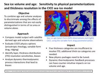
Concentration Decay Method Air Change Rate: In the case of zero inlet concentrate and perfect mixing in the space ACH = (ln C2 - ln C1)/Δ(in hours) C1 = Tracer Gas Concentration at start of test C2 = Tracer Gas Concentration at end of test
Tracer gas result [minutes]
Decay Test • Advantages • Don’t need to release precise amount • Don’t need to measure volume (if Cout = 0) • Disadvantages • Need to keep building well-mixed • Recontamination from buffer spaces • House needs to stay in one condition for entire test
How do you estimate uncertainty? • Use standard error of slope • Follow ASTM E741 • ΔACH < 10%
Advanced Tracer Gas Testing • Multi-zone flows • Easiest – Use several unique tracer gases • Harder – Use flow and mass balances
Consider Two-Zone Building º V4 º V3 º º V1 º V5 V3 or V6 º V2 V1 V2 vdA E • Tools • Mass balance on tracer gas • Mass (flow) balance on air • Measured concentrations in each space
Equations º º º º º º º º º º º º • How many unknowns? Equations? • Flow direction for interzonal flow • Air exchange rate for spaces • Sums of flows
Comments • Reduce mass balance to one equation by solving C2 equation for C1 and substituting into C1 equation • 2nd order ODE • Same thing for C1 equation • 5 unknown flows • Overall flow balance can be used to get four unknown flows • Measured tracer gas concentrations can be used to eliminate two more flows • Additional data needed for solvable system • Often use multiple tracer gasses
Single zone Example:Coffee Houses Lohaus and Waring (2006) ArE 381E Course Project
Example 2 Air distribution system efficiency • How well is outside supply air distributed to breathing zones in occupied areas? • Air exchange efficiency • ASHRAE Standard 129 – Measuring Air Change Effectiveness • Uses Tracer Gas Techniques • Age-of-Air Measurements
Why Worry About Good Mixing? Poor Mixing • Occupant complaints • ASHRAE Standard, Ventilation for Acceptable Indoor Air Quality • ASHRAE Standard is based on amounts of outside air getting to breathing zone not to supply air louvers Short – circuiting airflow patterns • Where a significant portion of supply air flows directly to the exhaust, bypassing the occupied portion (breathing zone) of the ventilated space.
Air Exchange Effectiveness • The definition is based on a comparison of the age of air in the occupied portions of the building to the age of air that would exist under conditions of perfect mixing of the ventilation air.
Age of Air • The age of the air at a give location is the average amount of time that has elapsed since the air molecules at that location entered the • building. • Amount of time outside air has been in an area • Two Methods of determination • Step-up constant tracer gas injection • Tracer gas concentration decay
How to measure Age of Air? Step down method: Injection and mixing • Air in the room is marked with tracer gas (injection and mixing) • Ventilation turned on Age of Air Measurements • Locations of interest • In the exhaust (C)
º º V V Cout Cin N Source Constant Injection V = N / (Cout - Cin) º You need to get to steady state injection
Constant Injection • Advantages • Can determine time-dependence of air exchange rates • Disadvantages • Need to keep building well-mixed • Recontamination from buffer spaces • Need to have mass flow controller • Need to measure volume (for ACH())
Average tracer gas level during test Tracer gas level at beginning of test avg age of air – Exhaust avg age of air – age of air in breathing zone E = How to measure Age of Air and Air Exchange Effectiveness Age of air at a location = Air change effectiveness (E) avg age of air = E = < 1.0 (less than perfect mixing) E = 1 (perfect mixing)
Significance of Air Exchange Effectiveness • ASHRAE Standard 62.1-2004 Ventilation for Acceptable Indoor Air Quality - Outside air requirements = QA/E as E decreases, OA should increase • US Green Building Council LEED Rating requires an E > 0.9 in all ventilated zones
Tracers which we use SF6 Gas analyzer • ppm with IR absorption or photo-acoustic IR • ppb with GC/ECD CO2 Tracers gas analyzer ( CO2 sensor )