Download
1 / 33
370 likes | 742 Views
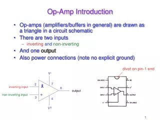
Op Amp Offset Voltage AEW-0100. Rev 1.2 Aug 2013. Input Offset Voltage. Input Offset Voltage. Offset Voltage Spec. and Distribution. Simulate Input Offset Voltage Look at the Test Conditions. OPA835. OPA835. Drift Slope – Positive and Negative. For this example Vos drift is defined:.

E N D
Op Amp Offset VoltageAEW-0100 Rev 1.2 Aug 2013
OPA835 OPA835 Drift Slope – Positive and Negative For this example Vos drift is defined:
Input Bias Current and Drift
Input Bias Current Input offset current: Ibos = Ib1 – Ib2 = 210nA – 150nA = 60nA
Simple Bipolar (No Ib Cancelation) Bias current in Bipolar amplifiers is from Base Current. It is typically larger then FET and it flows into the input terminals.
Bipolar with Ib Cancelation The input bias currents are mirrored and summed back in to cancel the bias current. This has the effect of significantly reducing input Ib. Note that when this is done, Ib can flow in both directions. Also Ibos is no longer smaller then Ib. Ibos = Ib1 – Ib2
Bias Current for CMOS Bias current in MOSFET amplifiers is mainly from leakage into ESD diodes.
OPA350 OPA277 Ib Over Temperature CMOS amplifier: In this case you see a dramatic increase in bias current at 25C. Note the logarithmic graph. Doubles every 10C. Bipolar amplifier: In this case you see a dramatic increase in bias current at 75C
Offset Lab • Simulation • Calculation • Measurement
Ex 1.1: Hand Calculations 1. Use the circuit and the excerpt of the data sheet below to calculate the maximum and tpical offset form vos.
Ex 1.1: Solution to Hand calculation This term is negligible Simplified equation has nearly the same result
Ex 2.1: Offset Schematic Two copies of the same two stage amplifier is on the board. Each two stage amplifier has four jumpers to configure the circuit.
Ex 1.1: Noise and Offset PCB Setup U0 = OPA2211 U1 = OPA2188 Note for this experiment Rin will be shorted. For the next experiment Rin will be connected between input and GND.
Ex 1.1: Instrument Setup OPA211 OPA188 211: 127mV 188: 54mV The instrument setup above will configure the signal source and scope for the circuit below so that we can see the I/O limitations.
Ex 1.1: Expected Results 1. Run a “analysis>dc analysis> calculate nodal voltages>” simulation to determine output offset. 2. How did the simulated results compare to the hand calculated results.
Ex 1.2: Hand Calculations (with Rin) 1. Use the circuit and the excerpt of the data sheet below to calculate the maximum and tpical offset form vos.
Ex 1.2: Amplifier I/O PCB Setup Change the Rin jumper settings.
Ex 1.2: Expected Results 1. Run a “analysis>dc analysis>calculate nodal voltages>” simulation to determine the output voltage from vos. 2. How did the simulated results compare to the hand calculated results.
Thanks for Your Time! Please try the Quiz.