Download

1 / 28
290 likes | 478 Views
MUSCLES Modelling of Un s teady Combustion in Low Emission Systems. G4RD-CT-2002-00644 R&T P roject within the 5 th Framework P rogram of the European Union. Time-Dependent Numerical Simulations of the One-Phase as well as the Multi-Phase Flow Fields within an LPP Aero-Engine System.

E N D
MUSCLESModelling of Unsteady Combustion in Low Emission Systems G4RD-CT-2002-00644 R&T Project within the 5th Framework Program of the European Union
Time-Dependent Numerical Simulations of the One-Phase as well as the Multi-Phase Flow Fields within an LPP Aero-Engine System
NastComb Code • CRFD (Computational Reactive Fluid Dynamics) code, extensively developed at DIMSET, and continuously improved and validated • Three-dimensional, turbulent, multi-phase, reactive flows • Ensemble-averaged, fully time-dependent (fast-transient tracking) numerical scheme • Main features: ALE method , TSDIA/MTS turbulence model, liquid-fuelspray simulation, fully detailed chemistry
NastComb: Spray Modeling • Stochastic technique • Discrete particles method • Collision, break-up, evaporation • TAB model • Taylor Analogy Break-up • Liquid droplet deformation
Only KH model with droplets stripping Jet primary breakup RTKH Model Stability analysis→Dispersion equation→Fastest growing wavelength • Kelvin-Helmoltz instabilities • Relative velocity • Rayleigh-Taylor instabilities • Interface acceleration RT+KH competition Secondary breakup
A First TAB/RT-KH Comparison • Primary jet break-up in stagnant gas
TAB Model - RTKH Model Compared RTKH model TAB model
TAB Model - RTKH Model Compared • TAB Model • SMR= 43 micron • Droplet N°= 6000 • RTKH model • SMR= 25 micron • Droplet N°= 20000
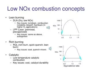
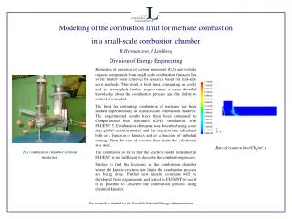
Combustionchamber Premixer Air inlet Ultra Low NOx “LRPM” Technology • Objective: to pursue NastComb calibration/validation in reactive conditions • Ultra-lean, fully-premixed combustion process with liquid fuels • Reduction of temperature levels (and gradients) to the advantage of Nox limitation • High flame-stability characteristics
Air flow rate 500 kg/h nominal, pc-controlled Burner-inlet air temperature 350 °C max, pc-controlled Thermo-chemical power 200 kW max, from fuel injection Equivalence ratio 0.42 nominal, ultra-lean, controllable Liquid fuel type Distillate #2 also: propane, gas-oil and jet-A Combustor pressure 1.15 bar nominal, sustainable up to 1.3 bar NOx level 10 - 15 ppm Fully verified in several test campaigns Electrical preheating power 110 kW max, pc-controlled SCL/LRPM Test Rig
Preheated Two-Phase Flow Simulation • Operative conditions adopted
TAB/RT-KH Comparison RTKH model TAB model
TAB/RT-KH Comparison RTKH model After RT effect TAB model
Spray Models and Implementation • NastComb solver is now provided with the RTKH model as a new option for improved predictions (unreactive and reactive) • Taking advantage of the very recent experimental data referred to the enlarged-scale Avio LPP model-rig, a unique opportunity has become available in order to pursue detailed calibration and validation for both one-phase as well multi-phase pre-heated flows in real-application conditions . • With above validations, NastComb solver has attained a quite interesting, reliable, application potential
Time Dependent Prediction of the One-Phase Flow-Field Within an LPP Aero-Engine System MUSCLES Mid-Term Meeting, September 21st-22nd, 2004 Karlsruhe
LPP System Computational Conditions Experimental Test Rig Zmax =750 mm - Xmax =250 mm - Ymax =250 mm Computational Grid Grid type: Structured-Multiblock N° of total Blocks: from203 to 451 Geometry: Fully 3D° N° of total cells: from 994000 to 2450000 Boundary Conditions Mass Flow : 0.4 kg/s Static Temperature Inlet : 298 K Static Pressure Outlet : 101680 Pa
Computational Results and Validation Z= +30 mm Meridian Plane Time Dependent Numerical Results Meridian & Cross Section Planes Mesh Size : 2 450 000 Meridian Plane Mesh Size : 994 000 Traversing Z= +30 mm Mesh Size : 2 450 000 Ca Cr Ct
Computational Power LINUX CLUSTER “APOLLO” Cpu’s : 12 Athlon™ MP 2.0 GHz Ram : Master 2 Gb DDR 266 Slaves 1 Gb DDR 266 Storage Capacity : 480 Gb Network : 3COM ™ Gigabit
ANNEX 4 Time Dependent Prediction of the Multi-Phase Flow-Field Within an LPP Aero-Engine System MUSCLES Mid-Term Meeting, September 21st-22th, 2004 Karlsruhe
LPP System: Two Phase Flow Computational Conditions Boundary Conditions: AIR Total Pressure Inlet : 103520 Pa Total Temperature Inlet : 451 K Static Pressure Outlet : 101300 Pa Air Mass Flow Inlet : 0.46 Kg/s Boundary Conditions: FUEL Fuel : Ethyl Alcohol (liquid) Fuel Mass Flow Inlet : 0.0035 Kg/s Total Temperature Inlet : 293 K Droplets Diameters : 40 Cone Angle : 50° Droplets Velocity : 50 m/s Numerical Grid Grid type: Structured-Multiblock N° of total Blocks: from203 to 451 Geometry: Fully 3D° N° of total cells: from 994000 to 2450000 Zmax =750 mm - Xmax =250 mm - Ymax =250 mm
LPP System : Two-Phase Flow Computational Results Z= +100 mm Meridian Plane Time Dependent Numerical Results Cross Section Plane Mesh Size : 2 450 000 Meridian Plane Mesh Size : 994 000 Locations of measuring traverses
Droplets Trajectories in Cross Section Plane (Z= +100mm) (colour is local velocity level)
LPP System: Droplets Trajectories in Meridian Plane (colour is local velocity level)
Unsteady Droplets’ Trajectories (notice the repeated wall-rebounds, in premixer and in discharge chamber)
Azymuthally-Averaged Radial Distributions of the Droplets’ Diameters: Numerical-Experimental Cross Comparisons Locations of measuring traverses