Download
1 / 1
10 likes | 157 Views
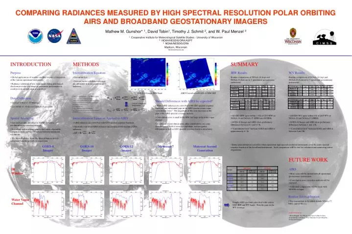
GOES-8 Imager. GOES-10 Imager. GOES-12 Imager. Meteosat-7. Meteosat Second Generation. IR Window. Water Vapor Channel. COMPARING RADIANCES MEASURED BY HIGH SPECTRAL RESOLUTION POLAR ORBITING AIRS AND BROADBAND GEOSTATIONARY IMAGERS.

E N D
GOES-8 Imager GOES-10 Imager GOES-12 Imager Meteosat-7 Meteosat Second Generation IR Window Water Vapor Channel COMPARING RADIANCES MEASURED BY HIGH SPECTRAL RESOLUTION POLAR ORBITING AIRS AND BROADBAND GEOSTATIONARY IMAGERS Mathew M. Gunshor* 1, David Tobin1, Timothy J. Schmit 2, and W. Paul Menzel 3 1 Cooperative Institute for Meteorological Satellite Studies - University of Wisconsin 2 NOAA/NESDIS/ORA/ASPT 3 NOAA/NESDIS/ORA Madison, Wisconsin * Mat.Gunshor@ssec.wisc.edu INTRODUCTION METHODS SUMMARY • Purpose • Global applications of weather satellites require a comparison of the various operational instruments. • Radiance validation of new instruments during post-launch checkout provides confidence in instrument performance or could provide an indication of a problem. • Intercalibration Equation • Geo minus Leo • Forward model calculated radiances are subtracted from measured mean radiances. • IRW Results • Routine comparisons of NOAA-14 (top) and NOAA-15 (bottom) to 5 operational geostationary instruments. • All GEO IRW agree within 1.0 K of LEO IRW on NOAA-14 and NOAA-15 (HIRS and AVHRR). • GOES-10 Imager and AIRS show preliminary differences between 0.1 and 0.3 K. • “Convolution Error” between GOES and AIRS is approximately 0.1 K. • WV Results • Routine comparisons of NOAA-14 (top) and NOAA-15 (bottom) to 5 operational geostationary instruments. • All GEO WV agree within 4 K of LEO WV on NOAA-14 and NOAA-15 (HIRS). • GOES-10 Imager and AIRS show preliminary differences between 1 and 2 K. • “Convolution Error” between GOES and AIRS is between 2 and 3K. GOES-10 Imager IRW Band AIRS Convolved w/GOES-10 IRW SRF • Data Collection • Geo/Leo within +/- 30 Minutes • Leo within +/- 10 degrees Lat/Lon of geo nadir • LEO = Low Earth Orbiting Instrument (HIRS or AVHRR) • GEO = Geostationary Orbiting Instrument • Mean = Measured Mean Radiance in Intercalibration Area • Clear = Forward Model Calculated Clear Sky Radiance • R = Radiance (mW/m2/ster/cm-1) • T = Temperature (K) • TCAL = Brightness Temperature Difference • B-1 = Inverse Planck Function Conversion From Radiance to Temperature • Should Differences with AIRS be expected? • When AIRS radiances are convolved with GEO spectral response functions, any substantial gaps in the AIRS spectra creates some “convolution error.” The magnitude of this error increases as the gaps in the AIRS spectral coverage increase. • Convolution error is small in the IRW, but large in the water vapor channel. • In addition to convolution error, other contributions can come from temporal, field of view size and shape, and navigation differences as well as GEO spectral response function uncertainty. Convert to Brightness Temperatures • Spatial Averaging • Geo and Leo data smoothed to 100 km (effective resolution) using a moving average. • Smoothing and averaging reduces the effects of possible navigation errors and the differences between instrument resolutions. • The Mean Radiance inside the Intercalibration Area is calculated from the spatially averaged data. • Intercalibration Equation Applied to AIRS • AIRS radiances are convolved with GEO spectral response functions. • Spectrally convolved AIRS radiances are compared with measured GEO radiances. • Better intercalibration is possible when operational high spectral resolution instruments cover the entire spectral response function of the broadband instruments. Such comparisons will be vital for validation and monitoring sensor degradation. FUTURE WORK • AIRS • More cases will be studied with all operational geostationary instruments. • Convolution error correction methods will be explored. • Additional comparisons will be made with MODIS on Aqua. • Routine Intercalibration • New instruments to be added include NOAA-17, MSG, and GOES-12. Sample AIRS spectrum convolved with various GEO IRW and WV bands. Note the gaps in the WV coverage. • Acknowledgements • Kevin Baggett, Jim Nelson, and Geary Callan for their programming assistance. Tony Schreiner for providing the background images.