Download
1 / 25
270 likes | 504 Views
Target Unit. Target Unit. Design a more reliable system for controlling lights and other devices. Power Line. Host Unit. 10:00. 9:59. Brian Roberts. Will Parker. Wai Yee Kwan. Jason Tatum. Leader: Brian Roberts Members: Will Parker Wai Yee Kwan Jason Tatum

E N D
Target Unit Target Unit Design a more reliable system for controlling lights and other devices. Power Line Host Unit 10:00 9:59
Brian Roberts Will Parker Wai Yee Kwan Jason Tatum Leader: Brian Roberts Members: Will Parker Wai Yee Kwan Jason Tatum Faculty Advisor: Dr. Nicholas Younan Dr. Nicholas Younan
Two classes of appliance control systems exist: inexpensive and costly. • Low end = poor reliability and limited accessibility • High end = high cost • Needed: a system that provides high-end features while retaining a low cost.
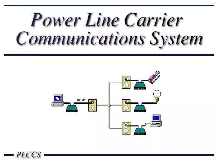
Internet/ LAN Host Computer Links the host unit to the Internet. Host Unit Sends commands to the target units. Target Unit Appliance Receives and executes commands. Target Unit Appliance Target Unit Appliance
Carrier Current Modem • Signal attenuation • Power line noise Power Supply • Voltage Regulation • Power Consumption
Signals attenuate when placed on a power line • Signal level at receiver must be > 3 mV • Line will contain noise that must be tolerated • Signal-to-Noise Ratio must be > 15dB
Received signal voltage Line length (m) Applied signal = 1.13V @ 71.5 kHz
2.5 0kHz 200kHz 71.5kHz 0.2V/div 0ms 2.5ms 5.0ms
Signal Noise 60kHz 71.5kHz 80kHz 60kHz 71.5kHz 80kHz Received signal = 7mV RMS SNR = 19.5dB Bit error rate is less than the required 0.01%
Power supply has to Provide +5V and +10V Have a ripple of less than 0.5VPP Use no more than 3W Power supplies considered: Shunt regulator Series regulator
Series Regulator Shunt Regulator
FCC regulation 15.109: Emissions @ 71.5kHz must be no more 33.6V/m @ 300m 3µV/m 0µV/m Field Strength 0m 125m 250m Line Length
Maximum allowed component cost for host unit is $35.00. Total is 23% less than requirement.
Maximum allowed component cost for target unit is $30.00. Total is 34% less than requirement.
Max. allowed field strength = 33.6 µV/m Simulated field strength = 3 µV/m Max. cost for host unit = $35.00 Actual cost for host unit = $26.91 Max. cost for target unit = $30.00 Actual cost for target unit = $19.69 Required signal = 3mV Signal @ 100m = 200mV Required max = 3W Simulated max = 2.6W Monthly cost = $0.22 Required SNR = 15dB Simulated SNR = 19.5dB Required voltages = 5V & 10V ± 10% Max. allowed ripple = 0.5V Simulated voltages = 5.2V & 10.2V Simulated ripple = 100mV Line Noise Voltage Regulation Signal Attenuation FCC Compliance Cost Power Consumption
Control a wider variety of devices. • Allow sensors to be present in target units. • Integrate existing automation standards such as X-10 and CeBUS into the system.
Dr. Nicolas Younan Dr. Joseph Picone Dr. Randy Follett A. Cohen, “Computers in use by Country,” Sales and Marketing Management, Vol. 150, No. 3, p.14, March 1998. C. Brown, “Home Smart Home,” Black Enterprise, Vol. 27, No. 8, pp. 87-89, March 1997. M. Shwehdi, “A Power Line Data Communications Interface Using Spread Spectrum Technology In Home Automation,” IEEE Transactions on Power Delivery, Vol. 11, No. 3, pp. 1232-1237, July 1996. S. Butler, “Smart Toilets and Wired Refrigerators,” US News and World Report, Vol. 126, No. 22, p. 48, 7 June 1999. E. Razzi, “Get Smart,” Kiplinger’s Personal Finance, Vol. 54, No. 1, pp.118-123, January 2000. P. Kingery, “Digital X-10,” http://gardentoys.com/htinews/feb99/articles/kingery/kingery- 13.htm, Leviton TelCom, USA, 1999.
X. Feng, “Home Networking,” ftp://ftp.netlab.ohio-state.edu/pub/jain/courses/cis788-99/home_nets/index.html, Ohio State University, USA, 1999. “Domosys Pricing,” http://216.208.231.80/pricing/, Domosys Corporation, Canada, 2000. “Echelon Open Systems 99 Special Offer,” http://www.echelon.com/tour99/Special.htm, Echelon Corporation, USA, 1999. ST7537 Home Automation Modem, http://us.st.com/stonline/books/pdf/docs/1787.pdf, STMicroelectronics, USA, 1995. COP8SAA7/COP8SAB7/COP8SAC7 8-Bit One-Time Programmable (OTP) Microcontroller, Literature # 102130-001, National Semiconductor Corporation, USA, August 1996. “Title 47, Part 15 – Radio Frequency Devices,” Code of Regulations, Federal Communications Commission, USA, 16 April 1999. “Understanding the FCC Regulations for Low-Power, Non-Licensed Transmitters,” OET Bulletin #63, Federal Communications Commission, USA, February 1996. COP8 Feature Family User’s Manual, Literature # 620897-003, National Semiconductor Corporation, USA, September 1996. J. Huloux and L. Hanus, Power Line Modem Application, http://us.st.com/stonline/books/pdf/docs/1124.pdf, STMicroelectronics, 1995.
P. Horowitz and W. Hill, The Art of Electronics, Cambridge University Press, New York, New York, USA, 1989. Z. Lau and M. Gruber, The ARRL Handbook: Seventy-Fifth Edition, The American Radio Relay League, Newington, Connecticut, USA, 1998. E. Hnatek, Design of Solid-State Power Supplies, Van Nostrand Reinhold Company Inc., New York, New York, USA, 1981. F. Mims, The Forrest Mims Engineer’s Notebook, LLH Technology Publishing, Eagle Rock, Virginia, USA, 1993. R. Pease, Troubleshooting Analog Circuits, Butterworth-Heinemann, Newton, Massachusetts, USA, 1991. LM78XX Fixed Voltage Regulator, http://www.fairchildsemi.com/ds/LM/LM7805.pdf, Fairchild Semiconductor Corporation, USA, 1999. Z. Yamayee and J. Bala, Electromechanical Energy Devices and Power Systems, John Wiley & Sons, Inc., 1994. “TDA5051A Home Automation Modem,” http://www.semiconductors.com/acrobat/datasheets/TDA5051A_2.pdf, Philips Semiconductors, Eindhoven, the Netherlands, 31 May 1999. “LM1893 / LM2893 Carrier-Current Transceiver,” http://www.national.com/ds/LM/LM1893.pdf, National Semiconductor Corporation, USA, April 1995.
“Products: SSC Power Line,” http://www.intellon.com/products/ssc/sscpower.html, Intellon Corporation, Ocala, Florida, USA, 2000. “1N4001 – 1N4007,” http://www.fairchildsemi.com/ds/1N/1N4007.pdf, Fairchild Semiconductor Corporation, South Portland, Maine, USA, 1998. “2N3904,” http://www.fairchildsemi.com/ds/2N/2N3904.pdf, Fairchild Semiconductor Corporation, South Portland, Maine, USA, 1997. “2N4401 NPN Small Signal Transistor,” http://www.vishay-liteon.com/datasheets/ds11103.pdf, Diodes Incorporated, Westlake Village, California, USA. “Serial-Interface Real Time Clock Module RTC-4553,” http://www.eea.epson.com/pdfs/rtc4553.pdf, Seiko Epson Corporation, Tokyo, Japan, 28 December 1998. “Serial-Interface Real Time Clock Module RTC-4543SA/SB,” http://www.eea.epson.com/pdfs/rtc4543.pdf, Seiko Epson Corporation, Tokyo, Japan, 28 December 1998. “I2C Bus Compatible Real Time Clock Module RTC-8583/8593 Series,” http://www.eea.epson.com/pdfs/rtc8583.pdf, Seiko Epson Corporation, Tokyo, Japan, 28 December 1998.
“Application Manual: Real Time Clock Module RTC-4553,” http://www.eea.epson.com/pdfs/rtc4553am.pdf, Seiko Epson Corporation, Tokyo, Japan. J. Huloux and L. Hanus, “ST7537 Power Line Modem Application,” http://us.st.com/stonline/books/pdf/docs/1124.pdf, STMicroelectronics, USA, 1995. R. Ziemer, W. Tranter, and D. Fannnin, Signals and Systems: Continuous and Discrete, Fourth Edition, Prentice-Hall, Upper Saddle River, New Jersey, 1998. “JS Power Relays,” http://www.aromat.com/jsbroch.pdf, Matsushita Electric Works, Ltd., Osaka, Japan, 1997. “G2R Power PCB Relay,” http://oeiweb.omron.com/oei/PDF/G2R.pdf, Omron Electronics Inc., Schaumburg, Illinois, USA, 1997. “G2R Power G5C Relay,” http://oeiweb.omron.com/oei/PDF/G5C.pdf, Omron Electronics Inc., Schaumburg, Illinois, USA, 1997. “24AA256 / 24LC256 / 24FC256 256K Bit I2C CMOS Serial EEPROM,” http://www.microchip.com/Download/Lit/Memory/IC/64to128/21203f.pdf, Microchip Technology Incorporated, Chandler, Arizona, USA, 1999. “FM93C86A 16Kbit Serial CMOS EEPROM (Microwire Synchronous Bus),” http://www.fairchildsemi.com/ds/FM/FM93C86A.pdf, Fairchild Semiconductor Corporation, South Portland, Maine, USA, February 2000.
“25AA640 / 25LC640 64K SPI Bus Serial EEPROM,” http://www.microchip.com/Download/Lit/Memory/SPI/21223d.pdf, Microchip Technology Incorporated, Chandler, Arizona, USA, 1999. “PartMiner Version 3.0,” http://www.partminer.com/, Partminer Inc., 1999. “+5V Powered, Multichannel RS-232 Drivers / Receivers,” http://pdfserv.maxim-ic.com/arpdf/1798.pdf, Maxim Integrated Products, Sunnyvale, California, USA, November 1999. COP8 Microcontroller Families, http://www.national.com/appinfo/mcu/index.html, National Semiconductor Corporation, Santa Clara, California, USA. T. Ramabadran and S. Gaitonde, "A Tutorial on CRC Computations", IEEE Micro, August 1988.