Download
1 / 91
910 likes | 1.01k Views
MBW-MQW in the LHC. C onsiderations on expected life and available options Presented by P. Fessia Fluka analysis: Francesco Cerutti, A nton L echner , Eleftherios Skordis Collimation input: R odrick B ruce, S tefano R edaelli , Belen Maria Salvachua Ferrando , Elena Quaranta

E N D
MBW-MQW in the LHC Considerations on expected life and available options Presented by P. Fessia Fluka analysis: Francesco Cerutti, Anton Lechner, EleftheriosSkordis Collimation input: RodrickBruce, Stefano Redaelli , Belen Maria Salvachua Ferrando , Elena Quaranta MNC team: Paolo Fessia, Pierre Alexandre Thonet, D. Tommasini Power Converter: Hugues Thiesen Optics: Massimo Giovannozzi MME design office: L. Favre, T. Sahner VSC: Eric Page, N. Zelko
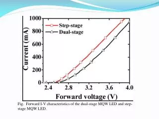
Screen design - For max effectiveness we have to target the higher possible density candidate therefore W, or better the alloys for machining - Magnetic properties can be an issue. Measurement being performed - Possible material staging along the MQW magnet length under study Inserts 5 cm long We cannot insert longer pieces because of he vacuum pipes flanges
Normalization: 1.15 1016 p (50 fb-1 ) Shielding effect Beam 2 Beam 2 MBW.B6R7 Flanges + Protection Beam 2 Beam 2 MBW.B6R7 With Flanges Normalization: 1.15 1016 p (50 fb-1 )
Optic change proposal point 7 discussed and agreed as possible with M. Giovannozzi (it needs verification) ABS
Magnet damage with shielding point 3 and 7, W shielding peak dose scaling IP 3 IP 7 Remove
Installation/planning/risks • To reduce radiation aging, the intervention, on most exposed magnets, shall performed in LS1 (also for ALARA reasons ). The initial foreseen modus operandi (directly on the magnet in the tunnel) is not feasible because of the interference with the backing equipment. Due to the limited number of vacuum chambers available and also field quality sorting, it is better to modify the magnets presently installed in LHC and replace them in the same slot. It will help in saving non radioactive spares. • The backing strips power wiring and the related thermocouples need to be rewired. VSC (N. Zelko) performed test and it looks feasible. Possible back up strategy with screen modification is available • Vacuum sector impacted • A6L7 no bake out yet because of the door project • B5L7: no bake out yet because of UA9 project • A4L7: no bake out yet because of UA9 project • A4R7: no bake out yet because of UA9 project • B5R7: already baked out • A6R7 no bake out yet because of door project • Possible planning sequence • 25/10 go or no go decisions (full, partial, nothing) • From the 28/10 magnet of L7 can go out to UX65 for buffer storage • From R7 can go out from the 11/11 to UX65 for buffer storage • Possible co activity with the fibre optic worksite in week 45 (4/11 to 8/11) and 49 (2/12 to 6/12) • 02/12 start of modification in the NormaLaP (867) • 03/02/2014: start of reinstallation • 01/03/2014 we need to have completed re-installation Total budget: 300 KCHF, procuring pieces for 12 units (4+4 to be installed, 2+2 spares)
ECR and documentation • ECR: completed and being checked by configuration management. Ready for approval process We will ask approval for • Applying the proposed intervention in LS1 (shielding installation on 8 magnets) • Approve the proposed actions for LS2 as baseline. New approval and complementary information are required before actual implementation. • Shield fabrication drawings approved in CDD. Shield support drawing under preparation
Conclusions • The proposed screen allow reducing of a factor 3 the dose and limit the number of magnet at risk or surely damaged, see previous slides. Hp. to achieve the same reduction factor on the spacers • The change of the optic in point 7 installing a long absorber is key to complete the protection • The lifetime of these units could be affected by the new environmental condition of point 7 not discussed here • The proposed shielding campaign should start in LS1 for effectiveness and ALARA • Very high dose dosimeter shall be installed systematically in point 3 and 7 to check better benchmark computations and symmetry effect • A campaign of irradiation of resins shall be performed with the real used resins and the relevant fillers in order to real know when the magnet will reach damage level • For HL LHC 4 MBW shall be reassembled with saddle type heads. This will solve the issue without needing special development • We need to check • For HL-LHC the MBW radiation dose along the straight part of the coil • The level of accumulated dose of the MBXW units • If any protection can be added to on the beam line for the MQWA.E4 in point 7 R and 7 L
Proton losses inventory and radiation effect on magnet(summary discussions with M. Brugger and f. Cerutti) • The year proton losses of 1.15 10^6 includes also MD (LHC Project Note 375 here the losses are assumed proportional to intensity and is the driving factor ). • Analysis (M. Brugger ) on the injected-dumped proton provides the following picture in 2012 (including also injection as long it was circulating) • For scrubbing the analysis was performed on the 25 ns run with a loss of about 6 10^14 protons per beam but taking into account the ratio with “physics” losses and energy scaling this should be negligible vs. the total magnet absorbed dose
7L extrapolation of dose to LS2 and LS3 Between 3 and 30 hours of work • Personal dose < 2mSv for Winter Shutdowns and operational period • Personal dose < 3mSv for Long shutdowns
Costs and delivery (based on offers) Remark: Copper pieces for 6 full magnets to cope with possible delayed delivery of W alloy Delivery with immediate order: Tungsten alloy pieces: 1st batch 8 weeks after reception order 2nd 2 weeks later (15/12/2013-06/01/2014) Copper pieces: 01/12/2013
Summary • The magnets and their circuits • The expected dose • Magnet radiation resistance • Protective actions • Shielding • Optics changes • The present “final” picture • Actions, planning risks, costs, documentation status
Dose evaluation process for each point IP 3 Fluka model results with 1.15 1016p lost per interaction point E 6.5 TeV. IP 7 1 (Flukaesti. already 7 TeV) Scale to 7 TeV (linearly) 1.077 1 Scale to the dosimeter readings as benchmark (TS2) 1 150 fb-1 ->3 350 fb-1 -> 7 3000 fb-1 ->60 Scale to the LS1, LS2 LS3 and HL-LHC integrated luminosity 150 fb-1 ->3 350 fb-1 -> 7 3000 fb-1 ->60 2 Scale to the increase slope dose/luminosity after TS2 2 Normalise to a total losses (adding the 2 points) of 1.15 1016 0.23 0.98->1 L=1 R=0.5 Scale to the Left and Right using RP survey L=1 R= (0.4->2)
Relationship dose vs. luminosity and point 7 vs. point 3 2 196.7/(697+196.7)=0.23 1357/(1357+30)
Analysis exp. data point 3 and point 7 1/100 1/6 43.7 kGy 19.1 kGy 5.5 kGy 1 2.3 kGy 1 18.0 kGy 1/3 1 15.7 kGy > 500 kGy 1/20 9.2 kGy 1/10 6.3 kGy 4.4 kGy RP survey IP7 RP survey IP3 397.5 kGy 7R/7L=B2/B1 487.3 kGy 3R/3L=B2/B1 119.8 kGy > 500 kGy 25.7 kGy 59.6 kGy 469.1 kGy 297.4 kGy 1.3 kGy 2.3 kGy 1.6 kGy 106.3 kGy 6.7 kGy 329.4 kGy fallen off (487.3 kGy) 100.4 kGy 81.7 kGy 8.0 kGy 297.4 kGy
8 7 6 5 4 9 10 3 11 2 1
Differentepoxy Aromatic > Cycloaliphatic > LinearAliphatic Aliphatic amine harderner poorradio-resistance Aromatic amine hardener> Anhydride hardener H: Too high local concentration of benzenemayinducesterichindrancedisturbation Good radio-resistance even if Cl (tendence to capture nth) • Novolac: HIGH Radio-resistance • Large nb of epoxy groups Density + rigidity • Glycidyl-amine: HIGH R.-resistance • Quaternarycarbon weakness • Ether group (R – O – R’) weakness E. Fornasiere Repl. by amina
Filler contribution 2 Categories of fillers: Powder fillers Glass/Silice fibers Paper [cellulose (C6H10O5)n] Strongdecrease of radio-resistance The bigger the powder, the more radio-resistant Hardenerchoice not influenced by filler High r.-resistance for Graphite and Alumina The more fillers, the more radio-resistant Best Radio-Resistantmaterials are obtainwith Glass/Silice (influence of boron) fibers and aromaticresins (Novolacand glycidyl-amine) E. Fornasiere
MQW • The pure resin mix used shall keep substantial mechanical properties at least till 15-20 MGy • Presence of glass fibre shall increase the substantial mechanical properties at least to 40-50 MGy
Spacers resins • Composition • HD polyethylene pipes filled with Assume a limit of 20 MGy
MBW BINP used resin. We looked at molecule and there is good indication that it should radiation hard as witnessed by the tests and we assume stresses of the order of 10 MPa MBW • The pure resin mix used shall keep substantial mechanical properties at least till 50-60 MGy (10 MPa) • Presence of fibre glass should probably extend life till 70-80 MGy
Screen design - For max effectiveness we have to target the higher possible density candidate therefore W, or better the alloys for machining - Magnetic properties can be an issue. Measurement being performed - Possible material staging along the MQW magnet length under study Inserts 5 cm long We cannot insert longer pieces because of he vacuum pipes flanges
Normalization: 1.15 1016 p (50 fb-1 ) MQW shielding effect Beam 2 Beam 2 Beam 2 Beam 2
MBWA - MBWB Peak Dose profile Beam 2 Beam 2 MBW.B6R7 Flanges + Protection MBW.A6R7 Flanges + Protection Beam 2 Beam 2 MBW.B6R7 With Flanges MBW.A6R7 with Flanges Normalization: 1.15 1016 p (50 fb-1 )
Optic change proposal point 7 discussed and agreed as possible with M. Giovannozzi (it needs verification) ABS
Magnet damage with shielding point 3 and 7, W shielding peak dose scaling IP 3 IP 7 Remove
Installation/planning/risks • To reduce radiation aging, the intervention, on most exposed magnets, shall performed in LS1 (also for ALARA reasons ). The initial foreseen modus operandi (directly on the magnet in the tunnel) is not feasible because of the interference with the backing equipment. Due to the limited number of vacuum chambers available and also field quality sorting, it is better to modify the magnets presently installed in LHC and replace them in the same slot. It will help in saving non radioactive spares. • The backing strips power wiring and the related thermocouples need to be rewired. VSC (N. Zelko) performed test and it looks feasible. Possible back up strategy with screen modification is available • Vacuum sector impacted • A6L7 no bake out yet because of the door project • B5L7: no bake out yet because of UA9 project • A4L7: no bake out yet because of UA9 project • A4R7: no bake out yet because of UA9 project • B5R7: already baked out • A6R7 no bake out yet because of door project • Possible planning sequence • 25/10 go or no go decisions (full, partial, nothing) • From the 28/10 magnet of L7 can go out to UX65 for buffer storage • From R7 can go out from the 11/11 to UX65 for buffer storage • Possible co activity with the fibre optic worksite in week 45 (4/11 to 8/11) and 49 (2/12 to 6/12) • 02/12 start of modification in the NormaLaP (867) • 03/02/2014: start of reinstallation • 01/03/2014 we need to have completed re-installation
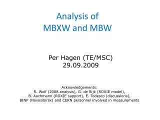
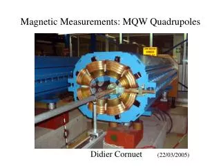
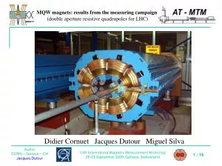
Magnetic qualification of Innermet 180 • 1st measurement provided by M. Buzio indicate a μr<=1.00002 • 2nd series of measurement with Innermet 180 inserts in a reference quadrupole to be performed this week • 3rd computations on the 2D MQW cross section of the MQW being performed by Per Hagen (TE-MSC-MDT) with a μr=1.00005 • Measurement of a spare magnet with and without shielding foreseen (but it will come late)
7L extrapolation of dose to LS2 and LS3 Between 3 and 30 hours of work • Personal dose < 2mSv for Winter Shutdowns and operational period • Personal dose < 3mSv for Long shutdowns
Costs and delivery (based on offers) Remark: Copper pieces for 6 full magnets to cope with possible delayed delivery of W alloy Delivery with immediate order: Tungsten alloy pieces: 1st batch 8 weeks after reception order 2nd 2 weeks later (15/12/2013-06/01/2014) Copper pieces: 01/12/2013