Download
1 / 21
210 likes | 319 Views
Team Hybrid. Member Subsystem Sean Frost Electric motor, motor controller, charge controller, charge accumulators Dan Farley Hydraulics system: Pumps, motors, valves, accumulators

E N D
Team Hybrid Member Subsystem Sean Frost Electric motor, motor controller, charge controller, charge accumulators Dan Farley Hydraulics system: Pumps, motors, valves, accumulators John Hoyt Internal Combustion Engine: Sensors, design of clutches for ICE and electric motor Hoyt
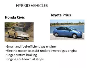
Battery Bank ICE ICE Generator Electric Motor Electric Motor ICE Generator Axle Assembly Axle Assembly Axle Assembly Power Split Device Background Information • Conventional drive train- torque is applied from an internal combustion engine • Hybrid vehicle drive train- An electric motor and/or an internal combustion engine can apply torque to the drive wheels Conventional Hybrid- Parallel Hybrid- Series Hoyt
Problem Statement: Vermont Technical College would like to compete in the Dartmouth Thayer School of Engineering Formula One Hybrid Racing Competition, but we do not currently have a vehicle that meets the specifications. Farley
Solution Statement: To develop and demonstrate a hybrid propulsion system which meets the following requirements Comprises both an internal combustion engine (ICE) and an electrical storage unit with electric drive The system shall meet all electrical specifications and requirements for the 2007 Dartmouth Thayer School of Engineering Formula One Racing Competition. The drive system may deploy the ICE and electric motor(s) in any configuration including series and parallel. Final design will allow the drive train system to be adapted to a chassis developed in a separate effort. Farley
Competition Overview There are three events in the competition: • Acceleration- teams compete for best time over a 75m sprint • Autocross- teams test car’s agility and performance in hill climbing, acceleration, cornering, stability, etc. • Efficiency- teams compete to maximize fuel efficiency while driving a set distance A three position selector switch will maximize performance and/or efficiency for each event Farley
Battery Bank Hybrid Propulsion System Overview • The rotational input from both the electric motor and ICE will drive hydraulic pumps • to pressurize the accumulator. The hydraulic pressure will act on hydraulic motors • positioned at the drive wheels to power the vehicle. • Regenerative braking will allow the hydraulic motors to pressurize fluid back into the • accumulator for future use. ICE Power Split Device 4 port, 2 way valve V+ Hydraulic Pumps Accumulator Hydraulic Motors Generator Accumulator V+ Axle Assembly Electric Motor Check valves LowPressure Feedback Frost
Electrical Motor/Generator & Controllers Subsystem (Control Sub-System) Manzanita Micro PFC-20 charge controller Belt connection To the ICE Electrical charge accumulator Generator V+ Frost Raptor 1200 Motor Controller Hydraulic Pump +120 VDC Electric Motor FB1-4001A Frost
Internal Combustion and Clutch/Pump Subsystem (Hydraulic Drive Sub-System) Electric Clutch ICE Hydraulic Pump Belt connection To the ICE V+ Electric Clutch Generator FB1-4001A #1 Clutch Control Signal Hydraulic Pump Battery Bank FB1-4001A #2 Hoyt
Hydraulic Pump 4 Port, 2 Way Electronically Controlled Valve Accumulator 2 Hydraulic Subsystem Overview (Hydraulic Driven Sub-System) 4 Port, 2 Way Electronically Controlled Valve Check Valve ICE Input Accumulator 1 Reservoir Electric Motor Input Hydraulic Motor Electronically Controlled Flow Valve Farley
Hydraulic Pump 4 Port, 2 Way Electronically Controlled Valve Accumulator 2 Hydraulic Subsystem Overview (Regenerative Braking Sub-System) 4 Port, 2 Way Electronically Controlled Valve Check Valve ICE Input Accumulator 1 Reservoir Electric Motor Input Hydraulic Motor Electronically Controlled Flow Valve Farley
Modes of Operation Full Acceleration µ-Controller Tire ICE Pressure (energy) OFF Standby Elec. motor OUTPUTS -Throttle actuated sol. -Hydraulic flow valves -Regen. Braking Assembly -Electric Motor speed Accumulator State Machine Efficiency Tire ICE Pressure (energy) Elec. motor • INPUTS • Shutoff switch • Battery Voltage • Motor Speeds • Fuel Supply • Mode selector • Brake switch • TPS • Regen. Braking switch Accumulator Regular Drive Tire ICE Pressure (energy) Elec. motor Accumulator Frost
Control System Acceleration 0101001101000 Output Description S0- Efficiency Default S1- ICE Control S2- Electric Motor Feedback S3- Drive Valve S4- ICE Feedback S5- Generator Clutch S6- Electric Motor Control S7- ICE-Hydraulic Pump Clutch S8- Generator-Battery Relay S9- N.O. Electric Relay S10- ICE Shutoff S11- Regenerative Valve S12- Regenerative Motor Clutch Regen. Drive 1000100001010 Standby 000000000000 HC08 Sensor Inputs Efficiency 1011111110010 Regen. Braking 1001100001011 Regular Drive 0111111111100 Farley
Control System 100 S5 S0 * S1 * ∑ Microcontroller Outputs * Throttle Request S4 S0- Efficiency Default S1- ICE Control S2- Electric Motor Feedback S3- Drive Valve S4- ICE Feedback S5- Generator Clutch S6- Electric Motor Control S6 * ∑ S2 * Frost
System Component Performance Curves Electric Motor/Generator Internal Combustion Engine Frost
VisSim System Simulation Frost
Refined • The current ICE power output would need to be upgraded by 6 to 7 times to meet the load requirements of the System. • The electronic generator would marginally fall short at certain operating conditions (i.e. full acceleration mode). • Determined the available sum of torques between the motors which was used to perform calculations to select the hydraulic components. Frost
Proof of Concept Due to cost and time limitations, two prototype subsystems were developed: • Power coupling and control of the ICE, electric motor, electronic clutches • Pneumatic model actuated by microcontroller which demonstrates drive mode and regenerative braking Hoyt
Proof of Concept – System I Power Coupling A parallel hybrid system allows the internal combustion engine and electric motor to operate independently or simultaneously. This prototype portrays the combination of power from the two motors and switches between series and parallel operating modes. This prototype will be used to test our motor control software in varying operating conditions. Generator/Alternator ICE Clutch Assembly Differential Battery Electric motor Hoyt
Manifold HC08 Stepper Motor Piston Pneumatic Motor Gas Brake Proof of Concept – System II Hydraulic (pneumatic) Drive Concept Team Hybrids’ particular design reveals a more unconventional method of regenerative braking. In order to effectively capture and distribute power, software has been developed for the system. This prototype was used to test the functionality and rationality of the software. Farley
Summary • Team Hybrid has designed a hybrid propulsion system that meets the required specifications for the Thayer School of Engineering Formula One Hybrid Competition. • A hybrid drive control system was developed and is demonstrated in two prototype subsystems to illustrate regenerative braking, power coupling and control of the ICE and electric motor. Farley