Download
1 / 33
330 likes | 433 Views
D0 Tracking – From the Inside Out. Opportunity to reflect on experience – what we wanted to achieve, where we succeeded and where we failed Outline RunII and it’s evolution Silicon Tracker Fiber tracker Muon system High luminosity effects Operations Conclusions.

E N D
D0 Tracking – From the Inside Out Opportunity to reflect on experience – what we wanted to achieve, where we succeeded and where we failed Outline • RunII and it’s evolution • Silicon Tracker • Fiber tracker • Muon system • High luminosity effects • Operations • Conclusions R. Lipton, Fermilab
Landscape circa 1990 • The Physics Landscape: • LHC/SSC will be on by 1997 and dominate high pt physics • Top quark not yet discovered • CDF shows B physics capability of collider detectors and utility of vertex detectors • B factories ? • Mixed high pT and B physics emphasis in design Let’s go back to 1990 – D0 wasconsidering an upgrade as theoriginal (RunI) detector was being installed to accommodate an upgraded Tevatron/Main Injector • Reduced crossing interval 3.2ms → 396(132) ns • Magnet – a break from the UA1 inspired no magnet philosophy • Improved tracking • Improved muon detector • Silicon vertex detector • Develop a tracking culture R. Lipton, Fermilab
Run One D0 Experience • Detailed MARS and Geant muon shielding simulations. • neutrons were a problem • complex shield design • timing important • Use small angle stereo in central tracker, small and large angle in silicon, short barrels • Add an inner scintillation counter layer to reduce muon pT threshold • Disk/barrel design of the silicon tracker to preserve high h resolution • Small angle muon chambers were very busy – can they be adequately shielded and keep good high h acceptance? • D0 tracker performed very poorly in rz – chambers used charge division and delay lines for z information. • CDF had much better J/y → mm yields than D0, due to thinner iron, lower pT. • Can good high h tracking be preserved in spite of the long luminous region? R. Lipton, Fermilab
132 ns 396 ns The Shifting Playing field 10 int/xing • Integrated luminosity 2 fb-1 →15 fb-1(IIb) →between 4 and 8 fb-1 • Crossing interval was planned to decrease from 396 ns to 132 ns in RunIIb. It will now stay at 396 ns • There was hope that the luminous region would decrease from 30 to 15 cm. • Actual instantaneous luminosity can be ~2x average due to bunch-to-bunch variations • Luminosity leveling? 8x10312x1032 5x1032 R. Lipton, Fermilab
Tracker hardware design was based on large acceptance in h. Used mixed disk/barrel system to maintain good resolution and efficiency with long (~25cm) luminous region Large area “H disks” – precise point at high Z to maintain momentum resolution Route cables between barrel ladders – no lost spaceat the barrel/disk interface Resulted in a complex silicon mechanical design and a challenge to the Monte Carlo Tracker Design R. Lipton, Fermilab
D0SMT Disk/Barrel Design Support andcables disk barrel R. Lipton, Fermilab
The D0 Run2 Detector Muon System Fiber Tracker D0SMT R. Lipton, Fermilab
Tracker Technology Decisions • Original silicon detector design was for 2 fb-1. RunIIb physics studies (Higgs) indicated that experiments (and accelerator) should attempt 15 fb-1 (2002) • Silicon technology was based on SSC R&D (double-sided) subsequent LHC R&D showed this was not the best choice • Rad hard chip technology being phased out at many vendors • We had the ~last run at UTMC for SVX2 (1996) • Chip design tools poor • Replaced by deep submicron ~2002 • D0 decided to use SVX2 rather than SVX3 • Bird in the hand (~working chip … little did we know) • Did not need multiple buffering at L1 (now limit to trigger) • Too much work to develop simultaneous low noise readout/daq (probably true-big effort at CDF) • VLPC/SciFi development for tracking – all new technology – high risk but excellent for fast triggering R. Lipton, Fermilab
Tracker Parameters • [s(pT)/pT]2 ~ 0.0152 + (0.0014pT)2 • s(PV) ~35 mm • s(IP) ~15 mm, pT >10 GeV Maximum 12 hits at h=0ignoring overlaps R. Lipton, Fermilab
Time in store noisy F-Wedges 'good' F-Wedge SMT Operations F wedge noise • SVX2 chip is not very robust • Needs to be read out every ~30 seconds or current goes up causing trips– heartbeat trigger installed • Very sensitive to supply voltage, signal quality • Channels come and go ~ 15% disabled at any one time • Wedge detectors from Micron show serious “grassy” noise – beginning several months after the start of RunII bias current R. Lipton, Fermilab
Microdischarge • Many double sided detectors have low p-side microdischarge junction breakdown voltage • Limits voltage applied to a side – not total bias • The sensitive side switches from p to n after type inversion • The total voltage allowedincreases after type because the oxide chargelowers the n-side fields • Not yet a practical limit tooperations R. Lipton, Fermilab
Booster Radiation Studies • Spare detectors were exposed to 8 GeV booster proton irradiation • Full readout/laser test measurements at each point • Most behaved “normally” • Double metal 90 degree detectors (DSDM) showed anomalous Vbias slope limit to SMT lifetime? 1 fb-1 R. Lipton, Fermilab
L3 DSDM L1 DSDM L4 DS L2 DS SMT Radiation Studies • We now have enough experience to measure long term behavior • Use charge collection and n-side noise • Charge collection data taken at regular intervals • DSDM detectors now look normal – probably charge annealing in PECVD dielectric • Expect the SMT to survive to 5-7 fb-1 R. Lipton, Fermilab
Vdepletion Warm-up during shutdown SMT Radiation Studies • Measure flux using leakage current evolution • Measure depletion voltage with charge collection and noise Noise vs voltage R. Lipton, Fermilab
Run II Results R. Lipton, Fermilab
2003 beam loss incident Beam Protection • Beam losses are not uncommon • 2003 CDF Roman Pot into beam • Kicker prefires, Quenches, Shot setup • LHC/TeV ~ 1000 in beam power • D0 has two radiation monitoring/abort systems • BLM - argon gas ion chambers circa 1980 • Originally developed for AD/CDF • Provides Tevatron abort@12 rad/s • 10 m from IP • NIKHEF finger diodes • 24 one cm photodiodes 2.6 cm to 9.5 cm from beam • 106 dynamic range – scaler/ADC • Not used for abort due to SMT readout noise Holes in 2 upstream components R. Lipton, Fermilab
Beam Monitoring • Large dynamic range and low radius of the fingers allow detailed studies of beam effects and incidents • Understand losses at various stages of the cycle – for some losses have dominated by luminosity Scaler count rate vs time as solenoidramps down – looper plateau ~0.8 T Finger scalers Finger ADCs Shot Setup R. Lipton, Fermilab
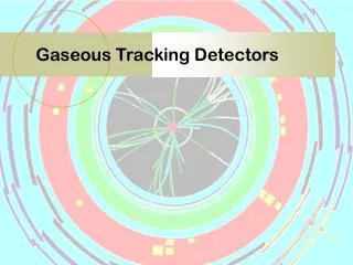
Fiber Tracker – CFT/CPS • CFT - 8 doublet layers of 0.835 mm fibers (xu,xv..) use high QE VLPC technology • Few layers-require high e • High occupancy for inner layers • Fewer hits than gas-based chamber, but more radiation hard, amenable to fast (L1) track trigger with FPGAs • CPS – layer of triangular scintillator outside of solenoid Fiber tracker Clear waveguides R. Lipton, Fermilab
Mean pedestal (ADC) CFT Operations • AFE – readout of VLPC system for CFT and preshower • SVX2 dynamic range ~200 MIPS front end integrator is subject to saturation at high L • Discriminator crosstalk to ADC • Crossing-to-crossing pedestal variations • Replacing AFE with AFEII • No SVX2 • New trip-t chip – clean discriminator output and timing crossing R. Lipton, Fermilab
Tracking Performance Low momentumtracking option de/dx particle ID R. Lipton, Fermilab
No Shielding D0 Shielding Muon System Muons are at the heart of much D0 physics • Run II optimization • Chambers at high h were too noisy • Most noise hits are out of time with collision muons • Detailed study/model of shielding • Lower pt threshold for B physics to ~1.5 GeV • Detailed shielding redesign • 50 cm of steel – hadrons and e/g • 12 cm of polyethylene - neutrons • 5 cm of lead - gamma rays • Reduction in particle fluxes by a factor of 50-100 (GEANT/MARS) • Run 1 muon detector occupancies have been in the 5-10% level • Run 2 muon detector occupancies are in the 0.05-0.1% level R. Lipton, Fermilab
Run I Small angle muon chambers “Typical” Run I event Run II R. Lipton, Fermilab
Muon Chambers and Counters R. Lipton, Fermilab
Muon System • Added fast counters to reject halo • Added counter layer before m filter with 1.5 GeV Pt threshold • Level 1 muon-track match trigger • Result: x150 J/y yield over Run I competitive B physics Run 1 Muon h in J/psi events R. Lipton, Fermilab
Monte Carlo • Difficult to properly model complex SMT cable paths • Use e+e- conversions to map material and validateMC • Initial version was missing top of support cylinder • Inclusion of ladder and support details is an ongoing effort • Tracking system resolutions and errors still not fully understood. Data Monte Carlo R. Lipton, Fermilab
Understanding Uncertainties • Are the assigned uncertainties correct? • Hit position algorithm based on cluster size • Study IP resolution of PV tracks based on hit patterns • Scale to fit beam convoluted IP distribution • Hampered by the loss of raw hit data early in the data stream R. Lipton, Fermilab
Tracking CPU • Tracking CPU time has always been a problem in this design – minimal layer in outer tracker • Currently our L3 rate is limited to 50 hz - the rate at which data can be reconstructed – will be raised • Serious problem at high luminosity Black = total tracking Red = pattern rec Green = HTF patt rec Blue = AA patt rec Pink = track fit HTF, not AA, is the current “culprit” Improvement by better treatment of large (looper) clusters R. Lipton, Fermilab
0 MB 4 MB 8 MB High Luminosity Tracking With our current hardware and algorithms both efficiency and purity will degrade at high luminosity R. Lipton, Fermilab
Study of Luminosity Effects in Data J/y →mm as a function of the number of tracks in the event R. Lipton, Fermilab
Coping with High Luminosity • AFE II project (CFT readout) • Fix saturation, pedestals, add timing to CFT • Layer 0 (M. Weber) • Tracking algorithms – tradeoffs between thresholds and speed • Luminosity leveling – vary b during the store to provide uniform luminosity with similar integral • Trigger upgrades R. Lipton, Fermilab
Operations • Experiment is collecting data efficiently ~ 5% dead time • Solenoid magnet developed a heat leak – limited to ~96% of full field • Limit thermal and ramp cycles • Operational channels • SMT ~ 87% • CFT ~ 99% (was 99.9%) • Muon – 99.8% • CAL ~ 99.9% R. Lipton, Fermilab
What we did .. Right • Carefully tested most detector types – extensive system tests • Excellent mechanical quality and stability • Tracking system provides excellent h and momentum acceptance, tracking to 180 MeV • Muon system design shielding and timing • It all works to produce physics Wrong • Upgrade was ambitious – all detectors should be properly supported in hardware and software • Hardware and software groups did not always interact effectively. • Cost and schedule was too much of an early concern • Changing plans from FNAL and accelerator R. Lipton, Fermilab
Conclusions Bs mixing WZ → trileptons W mass B semileptonic R. Lipton, Fermilab