Download
1 / 15
190 likes | 426 Views
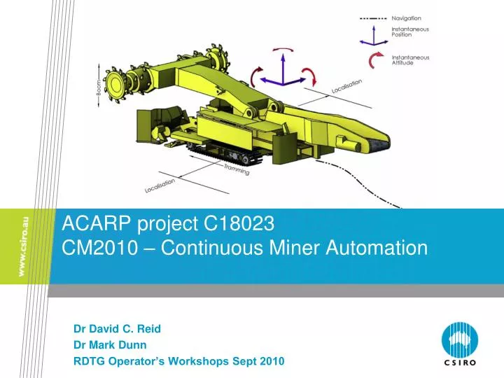
ACARP project C18023 CM2010 – Continuous Miner Automation. Dr David C. Reid Dr Mark Dunn RDTG Operator’s Workshops Sept 2010. Project Overview. Project context CM Automation component of the CM2010 initiative Project grand goal

E N D
ACARP project C18023CM2010 – Continuous Miner Automation Dr David C. Reid Dr Mark Dunn RDTG Operator’s Workshops Sept 2010
Project Overview • Project context • CM Automation component of the CM2010 initiative • Project grand goal • A remotely supervised continuous miner for roadway development • Project impact • Essential and major component of CM2010 goals • Immediate health and safety benefits • Immediate productivity benefits • We are now halfway through 3 year project
Enabling Technology • Need to develop navigation system suitable for accurate control of CM • Can’t use GPS underground (without a lot of additional infrastructure) • Technology needs to be physically robust, reliable, accurate and ideally self-contained (doesn’t rely on external infrastructure) • Technology needs to work under all normal CM operating conditions • Inertial navigation meets most of the above criteria • Already proven in longwall mining automation (but higher performance required for CM automation) • Reasonably self contained (but needs odometry/velocity aiding) • Has the additional benefit of providing real-time accurate CM pitch/roll/heading information at the CM • Need to develop a non-contact odometry solution for this system to be practical
CM Navigation Solution: INS + Odometry INS IMU Navigation Equations Position (AT, CT, VT) Gyros Accels Orientation (Heading pitch Roll) Odometry Aiding Source Process Environment • Presently evaluating INS and Odometry Solutions
Non-Contact Odometry • Inertial navigation system requires an external aiding source to achieve required position accuracy • An accurate non-contact odometer is key to practical CM navigation system: • Needs to be non-contact to be practical • Needs to be rugged-isable • Needs to be immune/tolerant to dust, moisture, vibration • Needs to be very accurate – navigation algorithms are very sensitive to latency (<40mS), accuracy, timing and measurement jitter • Multi-sensor solution provides redundancy benefits
Non-contact Odometry Technologies Mono Stereo Multi Multibeam 3D Scanning Point Doppler e-Steering UWB
Results so far • A CM navigation system has been developed • Non-contact odometry solutions have been developed for velocity aiding using hybrid technologies • Ultra low speed Doppler radar • Optical flow position sensor (like an optical mouse) • A skid steer vehicle The Phoenix has been customised for evaluating the navigation system performance
Mobile CM Test Platform: The Phoenix Non-contact optical flow odometry and very low speed Doppler radar
Test Platform Development: Phoenix • Phoenix provided a realistic CM-like platform for VMS-aided navigation testing • Installation of RTK GPS equipment on Phoenix for ground-truth reference • Installation of RTK surveyed base station at QCAT and radio link to Phoenix • Doppler radar and optical position sensor installed • Sagem Sigma30 INS installed • Custom-developed control and communication systems installed • Navigation experiments conducted on both paved and unpaved (rough) tracks
Results: CM Attitude Monitoring Accurate heading/pitch/roll information available on CM
Phoenix Navigation Testing Area • Test tracks – monorail/paved road and rough unpaved track
Phoenix Navigation Testing • [external video]
Next Stages • Further enhancement to the navigation solutions • Additional evaluation with lower performance inertial system • Further control system development • Development of Mine-To-Plan software tool • Field trials • Quarry • Underground
Summary • A practical CM navigation systems has been developed and demonstrated under limited operating conditions • New non-contact odometry technologies have been demonstrated • Further development and testing required under more realistic operating conditions
Thank you Contact Us Phone: 1300 363 400 or +61 3 9545 2176 Email: enquiries@csiro.au Web: www.csiro.au Exploration and Mining Dr David C. Reid Principal Research Engineer Dr Mark T Dunn Research Engineer Phone: 07 3327 4437 Email: david.reid@csiro.au