Download
1 / 49
500 likes | 745 Views
Mars Data Workshop Mars Express Radio Science MaRS Introduction Experiment, Operations, Observations Martin Pätzold, Silvia Tellmann Rheinisches Institut für Umweltforschung RIU Abt. Planetare Forschung Universität zu Köln ESAC 9th June 2008. Mars Express. Rosetta. Venus Express.

E N D
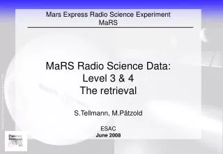
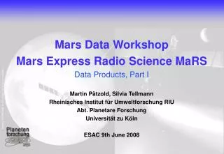
Mars Data Workshop Mars Express Radio Science MaRS Introduction Experiment, Operations, Observations Martin Pätzold, Silvia Tellmann Rheinisches Institut für Umweltforschung RIU Abt. Planetare Forschung Universität zu Köln ESAC 9th June 2008
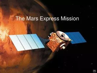
Mars Express Rosetta Venus Express 4 Years in Cruise 2 Years in Orbit 4.5 Years in Orbit 9. November 2005 14. April 2006 Launch: 2. June 2003 Arrival: 25. December 2003 3. March 2004 www.radio-science.de
Radio Science Experiments on interplanetary spacecraft Radio Science Experiments at RIU, Köln 35-m New Norcia Antenna Rosetta Mars Express Venus Express Mars Venus comets
What is Radio Science? What is Radio Science? • Radio Science is interested in: • Small changes in frequency (phase), signal power, • polarisation of a radio carrier signal, transmitted by a • spacecraft and received at a ground station on Earth
What is Radio Science? Was ist Radio Science? • ... You may conclude on... • ... the media which the radio signal propagated through • ... the perturbing forces acting on the spacecraft.
In the Beginning.... the basic idea Was ist Radio Science? • 1962 studies about radio propagation done at JPL • 1962 Review on Space Research, Iowa City • Von Eshleman, Stanford University • Bistatic Radar Astronomy • „one man´s noise is the other man´s data“
„Bistatic Radar Astronomy“ Was ist Radio Science? Interplanetary spacecraft ground station antenna • Idea: • ground station transmist radio signal • -> received by s/c • -> processed and analyzed on board • (radio spectrometer) • -> s/c transmits results via TM to Earth
realize.... Plan B Was ist Radio Science? oscillators, radio spectrometers with power and mass optimized for s/c were not available • Plan B: • s/c transmits radio signal, • G/S transmits and records, • process and analyze data at home • advantage: • use the onboard radio subsystem • no dedicated hardware • (well... Ok... later USOs) • problem: low RF power and SNR
well... back to... Plan APluto Kuiper – Belt (PKB) „New Horizons“ Science objectives PKB Radio Science: • Density, pressure, temperature of the neutral and ionized atmosphere of Pluto (Charon?) • Gravity field Pluto and Charon; separation of masses, bulk density • Radio Science Experiment (REX): • powerful uplink radio signal (X-Band) • signal processing on board • radio spectrometer, USO 1kg, 1W • results via TM to Earth • cooperation with Prof. G.L. Tyler, Stanford • University (Co-I contribution RIU Cologne) • launch 2006; Pluto flyby 2014
RF Functional Block Diagram Mars Express
RF Functional Block Diagram Venus Express Rosetta USO
Spacecraft High Gain Antennas Rosetta Mars Express Venus Express
S/C High Gain Antennas (HGA) Rosetta Mars Express Venus Express diameter 2,20m 1,70m 1,30 m X-band (8,4 GHz) gain 42 dBi 40 dBi 37 dBi RF Power 20 Watt 65 Watt 65 Watt EIRP 85 dBm 88dBm 85 dBm
NASA Deep Space Network 34 m BWG cluster, Goldstone 70 m 26 m 34 m HEF
What is Radio Science? Radio Science: observed parameters • radio carrier frequency shifts: • change of the relative speed between the ground station on Earth and the spacecraft (Doppler effect) • propagation of the radio signal in dispersive media • Change of the signal power by • absorption in media • scattering (particles and surfaces) • Change of polarisation by • reflection at surfaces (Brewster angle) • Faraday-Rotation in ionized media with external magnetic field
Frequency bands GPS ASTRA Telekomm. Sat. TV terrestrisch UKW (WDR Köln)
Radio Link Modes Mars Express Venus Express
Why two downlink frequencies? contributions to the received carrier frequency:
Why two downlink frequencies? contributions to the received carrier frequency: transmitted carrier frequency: X-band 8400 MHz S-band 2300 MHz
Why two downlink frequencies? contributions to the received carrier frequency: thermal noise; s/c radio subsystem G/S equipment sf~ order of mHz transmitted carrier frequency: X-band 8400 MHz S-band 2300 MHz
Why two downlink frequencies? contributions to the received carrier frequency: Doppler frequency term due to relative motion between s/c and G/S: vr~ 10 km/s: Doppler shift 280 kHz @ X-band Doppler shift 77 kHz @ S-band
Why two downlink frequencies? contributions to the received carrier frequency: changes in Doppler frequency due to gravitational and non-gravitational perturbing forces acting on the s/c Doppler frequency term due to relative motion between s/c and G/S: vr~ 10 km/s: Doppler shift 280 kHz @ X-band Doppler shift 77 kHz @ S-band
Why two downlink frequencies? contributions to the received carrier frequency: „plasma term“ due to the propagation of the radio signal through ionized media (solar wind, ionosphere) depends on the change of electron density along the ray path depends inversely on carrier frequency looks like noise => „plasma noise term“ sf~ order of mHz to Hz
Why two downlink frequencies? contributions to the received carrier frequency: bending of the ray path in media: depends on carrier frequency in the ionosphere independent on frequency in the neutral atmosphere Ionosphere: Dfbend,max~ 1 Hz Atmosphere: Dfbend,max~ -10 Hz (Mars); -4500 Hz (Venus)
Why two downlink frequencies? contributions to the received carrier frequency: bending of the ray path in the Earth´s troposphere and ionosphere: a constant or slight trend for the duration of observation will be corrected by models (GPS, Klobuchar) bending of the ray path in media: depends on carrier frequency in the ionosphere independent on frequency in the neutral atmosphere Ionosphere: Dfbend,max~ 1 Hz Atmosphere: Dfbend,max~ -10 Hz (Mars); -4500 Hz (Venus)
Why two downlink frequencies? contributions to the received carrier frequency: • there are contributions which are • proportional to carrier frequency • invers proportional to carrier frequency
Why two downlink frequencies? contributions to the received carrier frequency: • there are contributions which are • proportional to carrier frequency • invers proportional to carrier frequency a matter of fact: (it is not only designed like this, it is also a good idea)
Why two downlink frequencies? contributions to the received carrier frequency: compute: fS,rec – 3/11 fX,rec (differential Doppler) and apply baseline fit
Why two downlink frequencies? contributions to the received carrier frequency: compute: fS,rec – 3/11 fX,rec (differential Doppler) and apply baseline fit The differential Doppler is the frequency shift due to the propagation of the radio wave in a plasma relative to a one-way downlink at S-band
single frequency experiment feasible? • Is the experiment feasible at a single downlink frequency? • In principle, yes, but... • for gravity: at the cost of higher noise caused by the plasma • Higher plasma noise at S-band and lower Doppler SNR • Lower plasma noise at X-band and higher Doppler SNR compared to S-band • for the ionosphere: at the cost of a potential (small) bias in the electron density; refractivity and SNR stronger at S-band than at X-band • for the atmosphere: no effect (independent of frequency)
comparison differential Doppler atopposition & conjunction DOY 338, 2005 DOY 243, 2004
comparison differential Doppler atopposition & conjunction solar opposition: rms ~ 4.8 mHz DOY 338, 2005 solar conjunction: rms ~ 58 mHz DOY 243, 2004
Earth occultation • What is an Earth occultation? • As seen from the Earth, the s/c is disappearing behind the planetary disk and reappears at opposite hemisphere or opposite limb • Occurs at specific constellations between Earth & Mars location and orbit plane orientation • Occurs in „seasons“ • The radio signals propagate through the ionosphere and the atmosphere before the s/c is occulted • The radio link is interrrupted during the occultation proper • Mars Express can only observe the INGRESS into occultation
bending of the radio wave Earth occultation Ionosphere refractive index < 1 Neutral atmosphere refractive index > 1 Change of the propagation path! a a neutral atmosphere Mars ionosphere a: bending angle
Observables: Frequency Range Signal power Polarization Data types: Closed-loop Open-loop Data Pipeline DSN 35m, 70m ESA NNO 35m ESOC, Darmstadt, GE JPL, Pasadena, CA IGM, Cologne, GE Stanford U, CA NNO data processing, archiving DSN data processing
Data processing – the road to useful data Level 1a: raw data from the ground stations Binary or ASCII, in specific format Translation from L1a -> L1b Level 1b: extracted data from Level 1a ASCII, in defined format by radio science group
Data processing – the road to useful data Level 1a: raw data from the ground stations Binary or ASCII, in specific format Translation from L1a -> L1b Level 1b: extracted data from Level 1a ASCII, in defined format by radio science group Reconstructed orbit, frequency prediction from UniBw Munich
frequency prediction by Radio Science Simulator • Based on flown orbit => reconstructed orbit file • Compute expected received frequency at the ground station feed: • considering all motions: Earth, Mars, spacecraft, Earth rotation, plate tectonics • Consider relativistic frequency shifts • Correct for light times • Assume that Mars (Venus) has no atmosphere • Compute frequency residuals (received frequency minus predicted frequency) • Frequency residuals are precise up to 50 mHz (worst case); to be compared with 8400 MHz or 2300 MHz
Frequency residuals DOY 354, 2005
Frequency residuals DOY 354, 2005 start of obs. occultation lost radio link receiver noise
Frequency residuals DOY 354, 2005 bias of 29 mHz difference between observation and prediction 1-sigma standard deviation 32 mHz
Frequency residuals 2 minutes
Frequency residuals M1 main peak M2 neutral atmosphere ionopause
Occultation observed by a 70-m station same scale as before.... 1-sigma standard deviation: 3 mHz
Data processing – the road to useful data Level 1a: raw data from the ground stations Binary or ASCII, in specific format Translation from L1a -> L1b Level 1b: extracted data from Level 1a ASCII, in defined format by radio science group Reconstructed orbit, frequency prediction from UniBw Munich Level 2: frequency, Doppler residuals, differential Doppler, range, signal power; each frequency ASCII, timely ordered, calibrated; in defined format to be archived