Download
1 / 58
610 likes | 1.14k Views
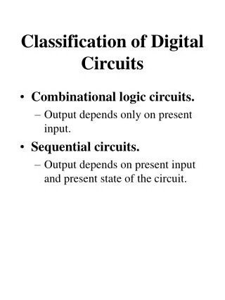
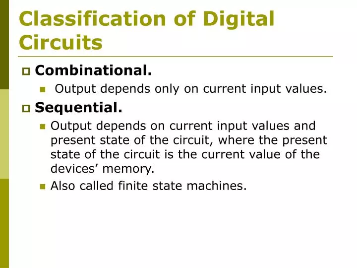
Classification of Digital Circuits. Combinational. Output depends only on current input values. Sequential. Output depends on current input values and present state of the circuit, where the present state of the circuit is the current value of the devices’ memory.

E N D
Classification of Digital Circuits • Combinational. • Output depends only on current input values. • Sequential. • Output depends on current input values and present state of the circuit, where the present state of the circuit is the current value of the devices’ memory. • Also called finite state machines.
State of a Circuit • The contents of storage elements. • A collection of know internal signal values that contain information about the past necessary to account the future behavior of the circuit.
Clock • Signal that determines the change of state in most sequential circuits.
Bi-stable Elements • The simplest sequential circuit. • It consist of a pair of inverters connected as shown below. Notice the feedback loop.
Digital Analysis • Two stable states. • If Q is HIGH then the lower inverter has a HIGH at its input and a LOW at its output. This in turn forces the upper inverter’s input to be LOW and its output to be HIGH. • If Q is LOW then the lower inverter has a LOW at its input and a HIGH at its output. This in turn forces the upper inverter’s input to be HIGH and its output to be LOW.
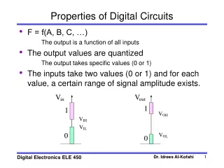
Analog Analysis • Considering the steady state behavior of the bistable element. • Vin1 = Vout2 • Vin1 = T(Vin2) • Vin1 = T(Vout1) • Vin1 = T(T(Vin1))
Analog Analysis • Metastable behavior: • Consider the middle intersecting point in the diagram shown below. • What would happen if a small amount of noise varies either input voltage.
Analog Analysis • The drawing on this slide shows a very good analogy to the stable and metastable behavior of a bi-stable element.
Latches and Flip-Flops • Binary cells capable of storing 1 bit of information. • Generates one of two possible stable states. • Two outputs labeled Q and Q’. • One or more inputs.
Latches and Flip-Flops • These sequential devices differ in the way their outputs are changed: • The output of a latch changes independent of a clocking signal. • The output of a flip–flop changes at specific times determined by a clocking signal.
S-R Latch • SR latch based on NOR gates. • The S input sets the Q output to 1 while R reset it to 0.
S-R Latch • When R=S=0 then the output keeps the previous value. • When R=S=1 then Q=Q’=0, and the latch may go to an unpredictable next state.
S-R Latch • Double negation is not a good idea. It is confusing and it creates problems.
S’-R’ Latch • S’R’ latch based on NAND gates. • The S’ input sets the Q output to 1 while R’ reset it to 0.
S’-R’ Latch • When R’=S’=1 then the output keeps the previous value. • When R’=S’=0 then Q=Q’=1, and the latch may go to an unpredictable next state.
S-R Latch With Enable • The outputs change only when the enable input C is asserted.
S-R Latch With Enable • Notice that the outputs only change when the input C is asserted.
D Latch • This latch eliminates the problem that occurs in the S’R’ latch when R=S=0. • C is an enable input: • When C=1 then the output follows the input D and the latch is said to be open. Due to this fact this latch is also called transparent latch. • When C=0 then the output retains its last value and the latch is said to be closed.
D Latch • For proper operation the D input must not change during a time interval around the falling edge of C. • This time interval is defined by the setup time – tsetupand the hold time – thold .
Edge Triggered D Flip-Flop • This flip-flop is made out of two D latches. The first latch is the master, and the second the slave. • When CLK_L= 1 the master is open (on) and the slave is closed (off). Qm and Ds follow Dm .
Edge Triggered D Flip-Flop • When CLK_L= 0 the master is closed, the slave is open and Qm is transferred to Qs . Note that Qs does not change if Dm changes because the master latch is closed leaving Qm fixed.
Edge Triggered D Flip-Flop • Positive edge-triggered D flip-flop. • Q* = D
Edge Triggered D Flip-Flop • If the set-up and hold times are not met the flip-flop’s output will go to a stable, though unpredictable, state.
Edge Triggered D Flip-Flop • Asynchronous inputs are used to force the output of the flip-flop to a particular state. • PR (preset) – Q = 1. • CLR (clear) – Q = 0.
Edge Triggered D Flip-Flop • Edge triggered D flip-flop with enable.
Scan Flip-Flop • This flip-flop allows its inputs to be driven from alternate sources, which can be very useful during device testing.
Master/Slave S-R Flip-Flop • The postponed output indicator shows that the output signal does not change until the enable C input is negated. • Flip-flops with this kind of behavior are called pulse-triggered flip-flops. • Q* = S+R’Q • SR = 0
Master/Slave J-K Flip-Flop • The J and the K inputs of the J-K flip-flop are analogous to the S and R inputs of the S-R flip-flop, except in the case where J=K=1. In this case the outputs of the J-K flip-flop will toggle to the opposite state.
Master/Slave J-K Flip-Flop • Q* = JQ’+K’Q
Edge Triggered J-K Flip-Flop • Q* = JQ’+K’Q
Edge Triggered J-K Flip-Flop • 74LS109
T Flip-Flop • Flip-flop changes state every tick of the clock. • Q* = Q’
T Flip-Flop With Enable • Flip-flop changes state every tick of the clock when enable is asserted. • Q* = ENQ’+EN’Q
Clocked SynchronousState-Machine Analysis • State machine – Another term for a sequential circuit. • Clocked – Refers to the fact that their flip-flops employ a clock input. • Synchronous – Same clock signal is used by all flip-flops. • A state machine with n flip-flops can have up to 2n distinct states.
State Machine Structure • State memory – a set of n flip-flops. • Next-state logic – combinational logic circuit which determines the next state. • Next-state = F(current state,input) • Output logic – combinational logic circuit which determines the output. • There are two models for the output logic: • Mealy Model. • Moore Model.
Mealy Model • The output is based on both current state and input. • Output = G(current state,input)
Moore Model • The output is based on current state only. • Output = G(current state) • In high speed circuits the output circuit may be absent and the output is generated directly from the flip-flop’s outputs. This is called output coded state assignment.
Mealy Model • Pipelined outputs – a design approach that ensures the output of a Mealy model circuit only changes with the clock.
Analysis • Determine the next-state and output functions F and G. • Use F and G to construct a state/output table that completely specifies the next state and output of the circuit for every possible combination of current state and input. • Draw a state diagram.
State Machines With D Flip-Flops • D0 = Q0 · EN’ + Q0’ · EN • D1 = Q1 · EN’ + Q1’ · Q0 · EN + Q1 · Q0’ · EN
State Machines With D Flip-Flops • Q0* = D0 • Q1* = D1 • Q0* = Q0 · EN’ + Q0’ · EN • Q1* = Q1 · EN’ + Q1’ · Q0 · EN + Q1 · Q0’ · EN
State Machines With D Flip-Flops • MAX = Q1 · Q0 · EN
State Machines With D Flip-Flops • Q0* = Q0 · EN’ + Q0’ · EN • Q1* = Q1 · EN’ + Q1’ · Q0 · EN + Q1 · Q0’ · EN • MAX = Q1 · Q0 · EN