Download
1 / 7
100 likes | 518 Views
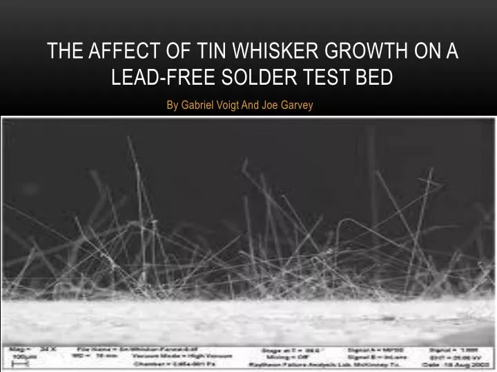
The Affect of tin whisker growth on a lead-free solder test bed. By Gabriel Voigt And Joe Garvey. Experiment rationale. Tin whiskers are a modern problem that can destroy any device with lead-free solder . They have destroyed planes and satellites, costing millions of lost dollars.

E N D
The Affect of tin whisker growth on a lead-free solder test bed By Gabriel Voigt And Joe Garvey
Experiment rationale • Tin whiskers are a modern problem that can destroy any device with lead-free solder. They have destroyed planes and satellites, costing millions of lost dollars. • Tin whiskers are thin crystalline structures that come from metal that is covered with tin, tin solder, or metal that is plated with tin. Tin whiskers are less likely to form on solder with lead in the alloy mixture, but lead is a health hazard. • Our team would like to send up a lead-free solder testbed and compare it to one that was left here on Earth. • A printed circuit board also would be sent and would be compared with an identical circuit board on Earth.
Materials 1. Type 1 FME (quantity of 2) 2. 12 cm x 0.5 cm tin-soldered printed circuit board (quantity of 2) 3. Circuit board printing machinery 4. Polyethylene foam packing cylinders for securing testbed in tube (Quantity of 4 cylinders; 0.5 cm in diameter, 1.27 cm in depth) 5. 99% pure tin bath 6. 12 cm x 0.5 cm Brass substrate (lead-free) 7. 50 volts of electric current 8. Plating machinery 9. Scanning electron microscope 10. Standard microscope
Experimental preparation Two FME’s would be prepared according to these specifications. One FME would stay on Earth, and the other would go to the ISS.
Data analysis • Data from both FME’s would be analyzed and compared. • The testbed would be examined with a scanning electron microscope to look for tin whisker formation. • We could continue to analyze the solder test bed and circuit board for many years. Tin whiskers can continue to form for years.
GROUND TRUTH EXPERIMENT • Since our experiment was not selected for spaceflight, our experiment could no longer conform to the research proposal due to lack of resources. • A metal solder testbed was created within the Type 1 FME. Lead-free solder covered the metal substrate. • The printed circuit board was eliminated due to financial constraints. • The Type 1 FME is in a secure location at room temperature. Substrate can be analyzed by a student microscope to look for tin whisker formation.
Acknowledgments Thank you to the Partners and Sponsors who made this experiment possible: Partners • Space and Naval Warfare Systems Command (SPAWAR) • Center for the Advancement of Science in Space (CASIS) • National Center for Earth and Space Science Education • College of Charleston • Medical University of South Carolina (MUSC) • National Oceanic and Atmospheric Administration (NOAA) Sponsors • ISHPI • CASIS • Palmetto Scholars Academy Board Members • Palmetto Scholars Academy Families