Download
1 / 20
200 likes | 571 Views
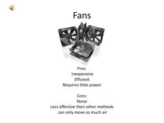
Fans. Fans. Purpose: To supply the necessary static pressure to move air in a ventilation or exhaust system. Basic classifications of air moving devices: Ejectors Fans. Ejectors. Low operating efficiencies.

E N D
Fans Purpose: • To supply the necessary static pressure to move air in a ventilation or exhaust system. Basic classifications of air moving devices: • Ejectors • Fans Fans
Ejectors • Low operating efficiencies. • Used only for special material handling applications (corrosive material, flammable material, hot or sticky material). • Used when not desirable to have contaminated air passing directly through the air moving device. • Used for air streams containing materials that might degrade fan performance. • Used in pneumatic conveying systems. Fans
Fans Primary air moving devices used in industrial applications Basic groups of fans are: • Axial fans • Centrifugal fans (home furnaces, hair dryers, vacuum cleaners) • Special type fans Fans
Axial Fans Propeller fans: • Moves air against low static pressures (less than 1” wg) • Commonly used for general ventilation • Very sensitive to added resistance • Blade types: • Disc blade • Propeller blade 2. Tube axial fans: • Moves air against moderate pressures (less than 2” wg) • Blade type: propeller type with no straightening vanes 3.Vane axial fans: • Moves air against high static pressures (up to 8” wg) • Limited to clean air applications • Blade types: air foil blades with straightening vanes Fans
Centrifugal Fans 1. Forward curved impellers: • Blades curve towards the direction of rotation. • Fans have low space requirements and low tip speeds. • Used against low to moderate static pressures. • Not recommended for dust or particulate that would adhere to blades. 2. Radial impellers: • Blades are in a radial direction from the hub. • Fan have medium tip speeds. • Radial blade shape resist material build up. • Can handle either clean or dirty air. 3.Backward inclined/curved impellers: • Blades are inclined opposite to the direction of fan rotation. • High fan efficiency and relatively low noise levels. • Blade shape is conducive to material buildup. Fans
Special Types of Fans 1. Inline centrifugal fans: • Backward inclined blades are used. • Pressure versus flow rate performance curves are similar to centrifugal fans. • Space requirements are similar to axial fans. 2. Power roof ventilators: • Packaged units that can be either axial flow or centrifugal type. • Centrifugal type discharges around the periphery of the ventilator. 3. Fan and dust collector combination: • Fans and dust collectors are packaged in a unit. Power exhausters and air foil are other special type fans. Fans
Fan Selection Considerations for fan selection are : 1. Capacity: • Flow rate based on system requirements. Expressed as actual cubic feet per minute (acfm). • Pressure requirement based on system pressure requirements. Expressed as FSP or FTP in inches of water gauge. 2. Air stream: • Material handled through fan. • Small amount of smoke or dust - backward inclined centrifugal or axial fan is selected. • Light dust fume or moisture - backward inclined or radial fan is preferred. • Heavy particulate loading - radial fan is selected. • Explosive or flammable material. • Spark resistant construction is used. • Explosion proof motor is used. Fans
Fan Selection 3. Physical Limitations: Fan size is determined by • Performance requirements • Inlet size and location • Fan weight The most efficient fan size may not fit the physical space available. 4. Drive arrangements: Electric motor is the power source of fans. • Unlike packaged fans, for larger units the motor is coupled directly to the fan or indirectly by a belt drive. Fans
Fan Selection Standard drive arrangements are: • Direct drive: • Offers more compact assembly and assures constant fan speed. • Fan speeds are limited to available motor speeds. • Belt drive: • Offers flexibility in changing the fan speed. • Important in applications where changes in system capacity or pressure requirements are needed. 5. Noise: • Generated by turbulence within he fan housing. • “White” noise which is a mixture of all frequencies is mostly produced. • Radial blade fans produce a pure tone at a frequency BPF. BPF = rpm * n * CF. Where: BPF - blade passage frequency. RPM - rotational rate. N - number of blades. CF - conversion factor, 1/60. Fans
Fan Selection 6. Safety and accessories: • Safety guards are required at inlet, outlet, shaft, drive and cleanout doors. • Accessories help in future maintenance requirements. • Flow control can be done using dampers. Outlet dampers: • Mounted on the fan outlet. • Adds resistance to the system when partially closed. Inlet dampers: • Mounted on the fan inlet. • Pre-spins air into the impeller. • Lowers operating horsepower. Fans
Fan Selection Various factors effecting fan selection are: • Volume required (cfm) • Fan static pressure • Type of material handled • Explosive or inflammable material • Direct driven vs belt driven • Space limitations • Noise • Operating temperature • Efficiency • Corrosive applications Fans
Rating Tables • Fan size and operating RPM and BHP can be obtained from these tables • Tables are based on the following pressure relationships FanTP = TP out - TP in = (SP out + VP out) - (SP in + VP in) FanSP = FanTP - VP out = SP out - SP in - VP in Refer to IV manual, table 6-1 (page 6-14) Fans
Point of Operation • Fan and system have variable performance characteristics which can be represented graphically. • “Point of operation” is the single point at the intersection of fan curve and system curve. Fan Performance Curves: • Curve represents fan performance variables plotted against flow rate. • Curve is specific to a fan of given size operating at a single rotation rate ( RPM ). • Even with size and rotation rate fixed, power and pressure requirements vary over a range of flow rates. System Requirement Curves: • Duct system pressure varies with volumetric flow rate. • Curve represents the variation of pressure plotted against volumetric flow rate. Fans
Fan Laws • Useful when changes in fan performance are required. • Principles relate the performance variables for any homologous series of fans. • Predict the effect of varying size, speed, capacity, pressure and power requirement as follows: Q2 = Q1 (size2/size1)3 (rpm2/rpm1). P2 = P1 (size2/size1)2 (rpm2/rpm1)2 ρ2/ ρ1. PWR2 = PWR1 (size2/size1)5 (rpm2/rpm1)3 ρ2/ ρ1. Fans
Simplified Fan Laws For changes of rotation rate: • Flow varies directly with rotation rate • Pressure varies as square of rotation rate • Power varies as cube of the rotation rate Q2 = Q1 (rpm2/rpm1) P2 = P1 (rpm2/rpm1)2 PWR2 = PWR1 (rpm/rpm) For changes of gas density: • Flow is not affected by a change in density • Pressure and power vary directly with density Q2 = q1 P2 = P1 (ρ2/ρ1) PWR2 = PWR1 (ρ2/ρ1) Fans
Limitations of Fan Laws Fan laws rely on the fact that the performance curves are homologous and the ratios are for the same relative points of rating on each curve. When applying fan laws to the following cases special care must be exercised. Case 1: when pressure does not vary as the square of the flow rate. Case 2: when the system has been physically altered or for some reason operates on a different system line. Fans
Fan Selection at a Density Other Than Standard Fan performance is affected by changes in gas density. • Corrections must be employed if density varies by more than 5% from the standard 0.075lbm/ft3 • Corrected Pressure is given by: Pe = Pa (0.075/ρa) Pe = Equivalent or corrected pressure Pa = Actual pressure ρa = Actual density, lbm/ft3 • Actual power requirement is given by PWRa = PWRt (ρa/0.075) PWRa = Actual power requirement PWRt = Power requirement in rating table. ρa = Actual density, lbm/ft3 • Fan selection at non-standard density requires knowledge of actual volumetric flowrate, actual pressure requirement and the density of gas at the fan inlet . Fans
Fan Installation and Maintenance • Fan rating tests are conducted under ideal conditions i.e.,uniform straight air flow . • In practice duct connections cause non-uniform air flow. • Location and installation of fan must consider the location of duct components to minimize losses. System Effect: • This is the estimated loss in fan performance due to non-uniform air flow. • System effect factor is obtained from resulting fan performance curve and actual system curve. A vortex or spin may be created by non-uniform flow conditions. • This may be caused due to poor inlet box, multiple elbows or ducts near the inlet. • If vortex or spin cannot be avoided, the use of turning vanes, splitter sheets will reduce the effect. Fans
Fan Installation and Maintenance Inspection and Maintenance: • Wear or accumulation on an impeller will cause weakening of the impeller structure . • Severe vibrations may cause damage or failure at the bearings or fan structure. Scheduled inspection of following items of fans is recommended: • Bearings for proper operating temperature • Excessive vibration of bearings or housing • Belt drives for proper tension and minimum wear • Correct coupling alignment • Fan impeller for proper alignment and rotation • Impeller free from excess wear or material accumulation Fans