Download
1 / 34
400 likes | 757 Views
SE464/CS446/ECE452 Documenting Software Architecture and Design. By Chang Hwan Peter Kim www.ece.uwaterloo.ca/~ece452 www.ece.uwaterloo.ca/~se446. Sources used in preparing these slides: Sample views for the PBX system by Sean Lau Ian Sommerville, Software Engineering, 6th edition

E N D
SE464/CS446/ECE452Documenting Software Architecture and Design By Chang Hwan Peter Kim www.ece.uwaterloo.ca/~ece452 www.ece.uwaterloo.ca/~se446
Sources used in preparing these slides: • Sample views for the PBX system by Sean Lau • Ian Sommerville, Software Engineering, 6th edition • Documenting Software Architecture: Documenting Interfaces, Bachmann et al., SEI • How to Write Doc Comments for the Javadoc Tool, Sun Microsystems • Documenting Component and Connector Views with UML 2.0, Ivers et al., SEI • Slides from last year’s course taught by Professor Czarnecki
Please note that the design document sample content used in these slides may not be complete or correct and should not be used without validation in your own project deliverables.
Overview • Basics of documenting software architecture and design • Views and Viewpoints • Design document for your class project • Logical View (sec 2.1) • Development View (sec 2.2) • Process View (sec 2.3) • Physical View (sec 2.4) • Interfaces (sec 3.0) • Data Schema View (sec 4.0) • +1 View (sec 7.0) • Further reading
Software Architecture and Design Documentation • The Software Design Document (SDD) captures the design of a system • At minimum, create a document describing the software architecture of a system (or be able to produce the document from a tool) • You may package it into a separate document called Software Architecture Document • A reasonable size for a Software Architecture Document for even a large system is 50-100 pages • Alternatively, you may produce a series of smaller working documents as you progress with the development
Software Architecture and Design Documentation • You may also capture the detailed design (in the SDD document or in a modeling tool) • It should be clear from a detailed design how to produce an implementation, but… • A UML rendering of the implementation code is not a design model (it’s an implementation model with limited value) • The gap between the architecture and the implementation for smaller systems may be small, so you won’t need a detailed design • Or you may need detailed design only for some parts or aspects of the system • Or your subsystems may be as big as to require their own architecture document
Overview • Basics of documenting software architecture and design • Views and Viewpoints • Design document for your class project • Logical View (sec 2.1) • Development View (sec 2.2) • Process View (sec 2.3) • Physical View (sec 2.4) • Interfaces (sec 3.0) • Data Schema View (sec 4.0) • +1 View (sec 7.0) • Further reading
The Need For Multiple Architectural Views • Architecture and design is about system structure • How the system is decomposed into parts • Components and interactions with appropriate properties, enabling appropriate analyses • But this begs the question: what kinds of structure? • Many possibilities: • Code structure • Run-time structure • Process structure • Work breakdown structure • Each of these can be the basis of a Design View (or Architectural View)
The Need For Multiple Architectural Views • Example: consider a building. • The contractor, the architect, interior designer, the landscaper, and electrician all have a different view of the structure of the building. • Although the view are pictured differently, all are inherently related. • Together they describe the building’s “architecture”. • Software exhibits many structures and it is difficult to communicate meaningfully about software unless it is clear which structure we are describing.
Kruchten’s “4+1 View Model” of the Architecture • P. Kruchten. The 4+1 View Model of Architecture. In IEEE Software, vol. 12, no. 6, November 1995, pp. 42-50, IEEE 1995 Note: The concrete selection of views for a given project may vary, but the main contribution of having to support multiple views and tie them back to the requirements remains.
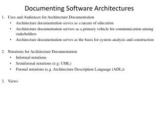
Basic Concepts in the IEEE Recommendation for Architectural Descriptions of Software-Intensive Systems (IEEE Std. 1471) • System stakeholder: “An individual, team, or organization (or class thereof) with interests in, or concerns relative to, a system.” • View: “A representation of a whole system from the perspective of a related set of concerns.” • Viewpoint: “A specification of the conventions for constructing and using a view. A pattern or template from which to develop individual views by establishing the purposes and audience for a view and the techniques for its creation and analysis.” • Software development organizations may decide to create their own libraries of viewpoints covering their usual needs
Overview • Basics of documenting software architecture and design • Views and Viewpoints • Design document for your class project • Logical View (sec 2.1) • Development View (sec 2.2) • Process View (sec 2.3) • Physical View (sec 2.4) • Interfaces (sec 3.0) • Data Schema View (sec 4.0) • +1 View (sec 7.0) • Further reading
Logical View (sec 2.1) • Use a component diagram to show provided/required interfaces and decomposition of components • Describe each component’s responsibilities • Other important information, e.g., • Dependencies • Non-functional properties (e.g., maximum memory usage, reliability, required test coverage, etc.) • Mandated implementation technology (e.g., EJB, COM, etc.)
CallProcessor AdminConsole Database Billing «component» «component» «component» «component» Logical View Example(using UML component diagram) IPhoneTester • May represent the process view if components are separate processes • Description • CallProcessor: interaction between phone processes • Provides an interface to test phones • AdminConsole: application logic and UI of admin application • Billing: bill generation and etc. • Database: persistence functionality • Provides a separate interface for hardware-related information • Variability • IDatabase may be a subinterface of IHardwareDatabase IBillGenerator IHardwareDatabase IDatabase
Development View (sec 2.2) • For each component, list • Source code artifacts (e.g., header file, C files, java files) used to build it • Note that a source artifact can be shared among more than one component (e.g., header files) • Deployment artifacts (e.g., exe file, jar archives, etc.) that represent the executable to be deployed on a computing node • May also list other artifacts such as documentation, test plans, etc. • Specify dependencies between artifacts, e.g., • Include dependencies between source artifacts • Make dependencies for deployment artifacts • May use tables and/or UML notation for artifacts and dependencies
Process View (sec 2.3) • Static and dynamic organization of executable program units (e.g. processes, threads) • If each component has its own process, then detailed information (e.g. thread organization and interaction) should be deferred to section 6 (Components)
Process View Example Exchanges call-related messages Returns phone test result <<Process>> CallMsgHandler 1 1 <<Process>> PhoneProcess 1 <<Thread>> HardwareTester <<Process>> AdminConsole 0..* 0..* 1..* • Note that despite the resemblance, the organization is different from the earlier component diagram • Explanation parts where necessary (e.g. cardinality of association ends between CallMsgHandler and PhoneProcess) • Dynamic organization (not shown) • Order of execution • A more detailed explanation of control/data dependency (e.g. through a scenario) • May use activity diagram / state chart Requests manual phone test, sets automatic test interval 1 0..* 1 Reads/writes generic data 1 <<Thread>> BillGenerator <<Process>> Database Reads/writes HW-related data 1 1 Reads/writes billing data 1 1
Physical View (sec 2.4) • Give a list of deployment artifacts; for each artifact, specify any deployment constraints (e.g., required hardware platform and resources) • Show how deployment artifacts are distributed over computing nodes • May use UML deployment diagrams
Physical View Example(using UML Deployment Diagram) From: Scott Ambler, The Object Primer 3rd Edition: Agile Model Driven Development with UML 2, 2004
Interfaces (sec 3.0) • Specification of observable interaction with the environment • All components have interfaces • A component’s interface contains view-specific information • Interfaces are two way: provided and required • Spectrum of interaction constraints • Simple existential dependency (e.g. requires resource X) to complex behavioural semantics (e.g. a protocol imposes a state-machine)
Interface Specification • Focus on observable interaction, rather than implementation • Possible elements • Signature (mandatory) • Description • Pre-condition • Post-condition • Side effects • Error-handling • Usage • Example or more formal specification (like a protocol statechart) • Variability • Non-functional requirements • Time-space constraints, usability constraints • Rationale and design issues • Above elements may be described per message/method and/or per interface
:CallMsgHandler[1..*] CallProcessor AdminConsole Database Billing :PhoneProcess[2..*] «component» «component» «component» «component» «component» «component» «component» Interface Example IPhoneTester IBillGenerator IHardwareDatabase IDatabase CallProcessor Programmatic interface ICallMsgHandler IPhoneTester 0..* 1..* <<delegate>> IPhoneProcess Message-based interface IHardwareDatabase <<delegate>>
Programmatic interface (Java) /** * @author chpkim * * <p>This interface provides database read/write facilities for generic * (accounts, billing, hardware, etc.) information. */ public interface IDatabase { /** * Establishes connection to this database. * * @precondition Database connection information should be set. * @postcondition Database connection should be achieved before returning to caller. * @throws SQLException * @nfr Connection pooling has not been considered. Concurrent access * is limited to table-locking, not row-locking. */ public void connect() throws SQLException; /** * Executes the specified statement on this database and return * the results if applicable. * * @param statement SQL statement to be executed * @return null if statement is not a query (does not start with SELECT). * non-null ResultSet otherwise. * @throws SQLException if query is malformed, connection is refused, etc. * @variability this method could be separated into two methods: * one for queries and one for non-queries */ public ResultSet execute(String statement) throws SQLException; } Defining custom tags: specify a desired order of tags to javadoc.exe -tag author -tag param -tag return -tag precondition:cmf:"Pre-conditions:" -tag postcondition:cmf:"Post-conditions:" -tag throws -tag nfr:a:"Non functional requirements:" -tag variability:a:"Variability:" -tag rationale:tm:"Rationale and Design Issues:" Heading that will appear Specifies where the tag is applicable to: Xaoptcmf (disable (X), all, overview, packages, types (interfaces, classes), constructors, methods, fields
Doclipse: javadoc support for Eclipse • Text-completion (like code-completion) • Define attributes on tags • Installation and more information: • http://www.beust.com/doclipse/
Why use javadoc? • Uniformity • Practical: industry-standard • Automatic formatting • Eliminates manual repetition • Interface documentation generated from implementation and included in design
Message-based interface ICallMsgHandler IPhoneProcess Idle Idle IPhoneProcess->ICallMsgHandler <RequestConnection> <IP>IP address</IP> </RequestConnection> RequestConnection [connection available && valid permission] / ConnectionApproved • Description: When phone is initially picked up, phone process requests connection • Pre-condition: Idle state • Post-condition: Grant or refusal with reason PhoneOffHook / RequestConnection OnHook / connections-- PhoneOnHook / OnHook Caller off hook Wait for digit ConnectionApproved Caller dial tone • When a precise protocol is an accompanying document, aim towards understanding, rather than being overly precise and formal • Runtime semantics may be included in “Behaviour” subsection of section 6.0 or in the interfaces section, as appropriate • May be specified for whole or part of an interface, as appropriate
Data Schema View (sec 4.0) • Provide a definition of all data structures referenced in the interfaces • Specify database schemas • May use UML class diagrams, ER diagrams, ASL, etc. • Be precise, especially in relationships • Cardinality (what is “many”? 1..* or 0..*?) • Primary, foreign keys
Data Schema Example (using ER diagram notation) FirstName Customer_ Account Name Customer Account 1 1..* LastName 0..* Account_ BillingPlan CreationDate CustomerId 0..1 Customer_Account BillingPlan • Does Account represent one or multiple phones?
+1 View (sec 7.0) • Explain how each use case is realized in the architecture by specifying the necessary interaction of components • Document component interaction as textual descriptions of event flow or UML interaction diagrams for each use case from the requirements specification
Example of a Scenario A request is made by the Call Handler to the Database Manager to acquire a channel
Keep in Mind… • These are just some examples of useful views; however,… • Some of these views may not be appropriate for a given system • The larger the system, the more dramatic the difference between these structures • For small systems, the module and conceptual structures may so similar they can be described together • E.g., no need for a separate process view if only one process in the system or one process per component • Some other kinds of views may be required for the system • E.g., control flow, data flow, timing, domain-specific views, etc. • You may also want to document mappings between individual views
Overview • Basics of documenting software architecture and design • Views and Viewpoints • Design document for your class project • Logical View (sec 2.1) • Development View (sec 2.2) • Process View (sec 2.3) • Physical View (sec 2.4) • Interfaces (sec 3.0) • Data Schema View (sec 4.0) • +1 View (sec 7.0) • Further Reading
Further Reading • Paul Clements (Editor), Felix Bachmann, Len Bass, David Garlan, James Ivers, Reed Little, Robert Nord, and Judith Stafford. Documenting Software Architectures: Views and Beyond. Addison Wesley Professional, ISBN: 0201703726; 1st edition, September, 2002