Download
1 / 46
540 likes | 985 Views
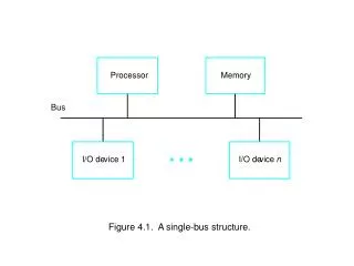
Processor - Memory Interface. Memory m ust be random access memory - memory in which individual memory locations can be accessed in any order at the same high speed. Memory. Instructions and data.

E N D
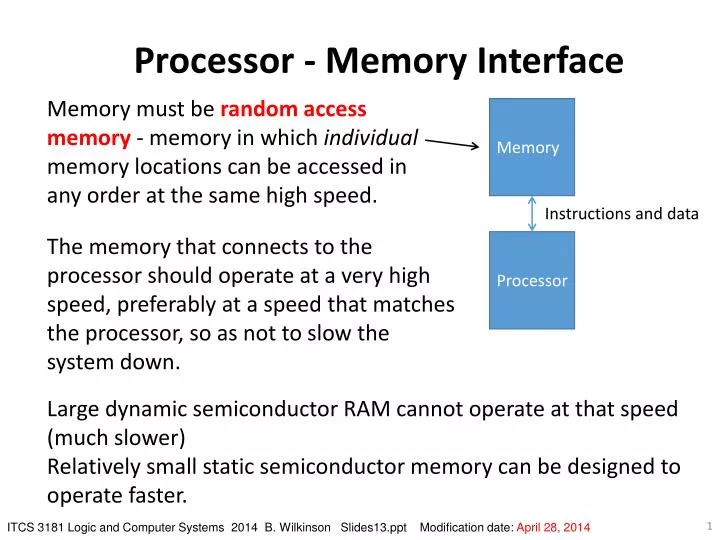
Processor - Memory Interface Memory must be random access memory - memory in which individual memory locations can be accessed in any order at the same high speed. Memory Instructions and data The memory that connects to the processor should operate at a very high speed, preferably at a speed that matches the processor, so as not to slow the system down. Processor Large dynamic semiconductor RAM cannot operate at that speed (much slower) Relatively small static semiconductor memory can be designed to operate faster. ITCS 3181 Logic and Computer Systems 2014 B. Wilkinson Slides13.ppt Modification date: April 28, 2014
Solution: Cache Memory Processor operates much faster than the main memory can. To ameliorate the situation, a high speed memory called a cache memory placed between the processor and main memory. Information must be in cache memory for processor to access it: M. Wilkes, “Slave Memories and Dynamic Storage Allocation,”IEEE Trans. On Electronic Computers, 1965. The first paper on cache memories.
If same instructions never re-executed, caches would cause an additional overhead as information would first have to be transferred from the main memory to the cache and then to the processor and vice versa, i.e. the access time, tawould be: ta = tm + tc where tc= cache access time tm= main memory access time. Fortunately, virtually all programs repeat sections of code and repeatedly access the same or nearby data. This characteristic is embodied in the Principle of Locality.
Principle of Locality Found empirically to be obeyed by most programs. Applies to both instruction references and data references, though more likely in instruction references. Two main aspects: 1. Temporal locality(locality in time) – individual locations, once referenced, are likely to be referenced again in the near future. 2. Spatial locality(locality in space) – references are likely to be near last reference. References to next location are sometimes separated into a third aspect, known as sequential locality.
Temporal locality found in instruction loops, data stacks and variable accesses. Temporal locality is essential for an effective cache. Spatial locality describes the characteristic that programs access a number of distinct regions. Sequential locality describes sequential locations being referenced and is a main attribute of program construction. Also seen in data accesses, as data items are often stored in sequential locations. Spatial locality helpful in the design of a cache but not essential.
Taking Advantage of Temporal Locality Suppose a reference is repeated n times in all during a program loop and, after the first reference, the location is always found in the cache, then the average access time would be: Average access time = (ntc + tm)/n = tc + tm/n where n = number of references. Example If tc = 5 ns, tm = 60 ns and n = 10, average access time would be 11 ns, as opposed to 60 ns without cache. THROUGHOUT tc is the time to access the cache, get (or write) the data if a hit or recognize a miss. In practice, these times could be different.
Hit Ratio – the probability that the required word is already in the cache. A hit occurs when a location in the cache is found immediately, otherwise a miss occurs and a reference to the main memory is necessary. Number of times required word found in cache The cache hit ratio, h, (or hit rate) is defined as: h = The miss ratio(or miss rate) is given by 1 - h. Total number of references
Average access time using Hit Ratio The average access time, ta is given by: ta = tc + (1 - h)tm assuming again that the access must be to the cache on a hit or miss before an access is made to the main memory on a miss. Also assume that tm includes sending to cache and to processor on a miss (could be overlapped). (Only read requests are consider. Write requests considered later) Example If hit ratio is 0.85 (a typical value), main memory access time is 50 ns and cache access time is 5 ns, average access time is 5+0.1550=12.5 ns.
Alternative equation ta = thit + (1 - h)tmiss_pen where thit = the time to access the data should be it in the cache (the hit time) and tmiss_pen is the extra time require if the data is not in the cache (the miss penalty), i.e. Average memory access time = hit time + miss rate miss penalty This form is used by Hennessy and Patterson (1996) – the computer architecture Bible.Our equations can be put in this form by simply substitution thit for tc and tmiss-pen for tm Machine cycles In a practical system, each access time given as an integer number of machine cycles. Typically hit time will be 1–2 cycles. Cache miss penalty in order of 5–20 cycles.
Taking advantage of Spatial Locality To take advantage of spatial locality, transfer not just one byte or word from the main memory to the cache (and vice versa) but a series of sequential locations called a line or a block. (Both terms are used in the literature – we shall use the term line.) For best performance, the line should be transferred simultaneously across a wide data bus to the cache. This also enables the access time of the main memory to be matched to the cache.
Taking advantage of Spatial Locality To take advantage of spatial locality, transfer not just one byte or word to/from main memory to cache but a series of sequential locations called a line or a block. For best performance, line should be transferred simultaneously across a wide data bus to the cache. This also enables access time of main memory to be matched to the cache. Cache memory with multiple memory modules (wide word length memory)
Cache Memory Organizations Need a way to select the location within the cache. The memory address of its location in main memory is used. Three ways of selecting cache location: Fully associative Direct mapped Set associative Memory Cache Data Memory address Processor
Fully Associative Mapping Both memory address and data stored together in the cache. Incoming memory address is simultaneously compared with all stored addresses using the internal logic of the cache memory.
Example Suppose each line has 16 bytes. With 32-bit processors, a word consists of 4 bytes: “Word” field specifies word within line. In this example, with 4 words in line, need 2 bits. “Byte” field specifies byte within word. In this example with 4 bytes in word, need 2 bits.
Selection/Replacement Algorithms Fully associative cache needs an algorithm to select where to store information in cache, generally over some existing line (which would have to be copied back to the main memory if altered).* Must be implemented in hardware. (No software) Ideally, algorithm should choose a line which is not likely to be needed again in the near future, from all lines that could be selected. Common Algorithms 1. Random selection 2. The least recently used algorithm (or an approximation to it). * Note in caches the selection and replacement location usually refers to the same location whereas in virtual memory (OS course) they usually refer to different locations.
Least Recently Used (LRU) Algorithm Line which has not been referenced for longest time removed from cache. The word “recently” comes about because the line is not the least used, as this is likely to be back in memory. It is the least used of those lines in the cache, and all of these are likely to have been recently used otherwise they would not be in the cache. Can only be implemented in hardware fully when the number of lines that need to be considered is small.
Direct Mapping Line held in cache at a location given by ”index” bits of main memory address. Line selected by index bits of main memory address. Most significant bits of address stored in cache compared with most significant bits of main memory address (tags):
Sample Direct-Mapped Cache Design 8192-byte direct mapped cache with 32-byte line organized as eight 4-byte words. 32-bit memory address. With 4 bytes in word, need 2 bits in byte field. With 8 words in line, need 3 bits in word field. With 8192 bytes in total and 32 bytes in each line, 8192/32 entries in cache (= 256 = 28). So index = 8 bits.
Advantages of Direct Mapped Caches No replacement algorithm necessary - because there is no choice in the selection of the location for the incoming line. It is given by the index of the address of incoming line. Simple hardware and low cost. High speed of operation.
Major Disadvantage of Direct Mapped Caches Performance drops significantly if accesses are made to different locations with the same index. However, as the size of cache increases, the difference in the hit ratios of the direct and associative caches reduces and becomes insignificant.
Set-Associative Mapping Allows a limited number of lines, with the same index and different tags, in the cache. A compromise between a fully associative cache and a direct mapped cache. Cache divided into “sets” of lines. A four-way set associative cache would have four lines in each set. The number of lines in a set is known as the associativity or set size. Each line in each set has a stored tag which, together with the index (set number), completes the identification of the line.
4-way Set-Associative Cache First, index of address from processor used to access set. Then, all tags of selected set compared with incoming tag. If match found, corresponding location accessed, otherwise access main memory.
Sample 4-way Set-Associative Cache Design 4096-byte 4-way set-associative cache with 8-byte line organized as two 4-byte words. 32-bit memory address. With 4 bytes in word, need 2 bits in byte field. With 2 words in line, need 1 bit in word field. With 4096 bytes in total and 8 bytes in each line and 4 lines in set (4-way set assoc.) 4096/(4 x 8) entries in cache (= 128 = 27). So index = 7 bits.
Set-Associative Cache Replacement Algorithm • Need only consider the lines in one set, as the choice of set is predetermined by the index (set number) in the address. • Hence, with two lines in each set, for example, only one additional bit is necessary in each set to identify the line to replace. • Set size • Typically, set size is 2, 4, 8, or 16. • A set size of one line reduces organization to that of direct mapping. • An organization with one set becomes fully associative mapping. • Set-associative cache popular for internal caches of microprocessors.
Valid Bits In all caches, one valid bit provided with each line.* Will assume one valid bit per line. Valid bits set to a 0 initially. Then set to a 1 when contents of line is valid. Checked before accessing line. Needed to handle start-up situation when cache holds random patterns of bits and also before cache is full. * Or parts of a line if only parts transferred in separate transactions)
Sample Cache Design showing valid bits (assuming a line can be transferred in one transaction) 4096-byte 2-way set-associative cache with 16-byte lines organized as four 4-byte words. 32-bit memory address. Valid bit set when line transferred into cache With 4 bytes in word, need 2 bits in byte field. With 4 words in line, need 2 bit in word field. With 4096 bytes in total and 16 bytes in each line and 2 lines in set (2-way set assoc.) 4096/(16 x 2) entries in cache (= 128 = 27). So index = 7 bits.
Fetch policy Three strategies for fetching lines from main memory to cache: Demand fetch - fetching a line when it is needed on a miss. Prefetch - fetching lines before they are requested. Simple prefetch strategy - prefetch (i + 1)th line when ith line is initially referenced (assuming that the (i + 1)th line is not already in the cache) on the expectation that it is likely to be needed if the ith line is needed. Selective fetch - policy of not always fetching lines, dependent upon some defined criterion. Then, main memory used rather than cache to hold the information. Individual locations could be tagged as non-cacheable. May be advantageous to lock certain cache lines so that these are not be replaced. Hardware could be provided within cache to implement such locking.
Write Policies Reading a word in cache does not affect it and no discrepancy between the cache word and copy held in main memory. Writing can occur to cache words and then copy held in main memory different. Important to maintain copies same if other devices such as disks access the main memory directly. Two principal alternative mechanisms to update the main memory: Write through Write back
1. Write-Through In the write-through mechanism, every write operation to the cache is repeated to the main memory, normally at the same time. Then main memory always the same as the cache.
Write-through equations With transfers from main memory to cache on all misses (read and write): ta = tc + (1 - h)tm + w(tm - tc) where tc = cache access time, tm= main memory access time, and w = fraction of write references. (tm - tc) is additional time to write word to main memory whether hit or miss, given that both cache and main memory write operations occur simultaneously but main memory write must complete before subsequent cache operation can proceed. Example Suppose tc = 5 ns, tm = 50 ns, h = 99 per cent, w = 20 per cent, and the memory data path fully matches the cache line size. The average access time would be 19 ns.
Two ways to handle write misses 1. Fetch-on-write (miss) Describes a policy of bringing a line from the main memory into the cache for a write operation on a miss (when the line is not already in the cache). The term allocate on write is sometimes used for fetch on write because a line is allocated for an incoming line on cache miss. 2. No-Fetch-on-write (miss) Describes a policy of not bringing a word/line from the main memory into the cache for a write operation. Also called Non-allocate on write. No fetch on write often practiced with a write-through cache. Why?
No-fetch-on-write equation for write-through cache The average access time given by: ta = tc + (1- w)(1 - h)tm + w(tm - tc) where tc = cache access time (hit or miss), tm = main memory access time, and w = fraction of write references. 1 - w= fraction of read references (not write) The hit ratio hwill generally be slightly lower than for the fetch on write policy because altered lines will not be brought into the cache and might be required during some read operations, depending upon the program. These equations are simplified and make assumptions.
Cache with write buffer Write-through scheme can be enhanced by incorporating buffers: Allows the cache to be accessed while multiple previous memory write operations proceed. “Non-blocking” store.
2. Write-Back (or copy back) Write operation to main memory only done at line replacement time. At this time, line displaced by incoming line written back to main memory. Step 2 Step 3 Bring in Y Step 1
Write-Back Equations “Simple” write-back: ta = tc + (1 - h)tm + (1 - h)tm = tc + 2(1 - h)tm One (1 - h)tmfor writing a line back to memory, other (1 - h)tmfor fetching a line from memory. Write-back normally handles write misses as fetch-on-write.
Write-Back with write back of modified lines Write-back mechanism usually only writes back lines that have been altered. The average access time now becomes: ta = tc + (1 - h)tm + wb(1 - h)tm = tc + (1 - h)(1 + wb)tm where wb is the probability that a line has been altered. The probability that a line has been altered could be as high as the probability of write references, w, but is likely to be much less, as more than one write reference to the same line is likely and some references to the same byte/word within the line likely.
Instruction and Data Caches • Several advantages if separate cache into two parts, one holding the data (a data cache) and one holding program instructions (an instruction cache or code cache): • Separate paths could be provided from the processor to each cache, allowing simultaneous transfers to both the instruction cache and the data cache. • Write policy would only have to be applied to the data cache assuming instructions are not modified. • Designer may choose to have different sizes for the instruction cache and data cache, and have different internal organizations and line sizes for each cache.
Particularly convenient in a pipeline processor, as different stages of the pipeline access each cache (instruction fetch unit accesses instruction cache and memory access unit accesses data cache):
General Cache Performance Characteristics Miss Ratio against Cache Size
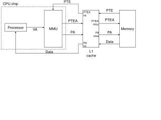
Second Level Caches Most present-day systems use two levels of cache (or three levels). First-level cache access time matches processor. Second-level cache access time between main memory access time and first level cache access time.
Strictly inclusive caches -- all the data in the L2 cache is also in the L1 cache Exclusive caches – data is guaranteed only to be in one cache (L1 or L2) at most, never in both. Alternative: data could be in only L1 or L2 or both.
Second level cache equation Can extend previous equations to cover second-level cache. Expanding tc in: ta = tc + (1 - h)tm we get: ta = [tc1 + (1 - h1)tc2] + (1 - h2)tm where: tc1= first-level cache access time tc2= second-level cache access time tmmain memory access time h1= first-level cache hit ratio h2= combined first/second-level cache hit ratio, considering two caches as one homogeneous cache system. Most microprocessor families provide for second-level caches.
Caches Example • Intel i3-2120 (Sandy Bridge), 3.3 GHz, 32 nm(Launched 2011) • L1 Data cache = 32 KB. 64 B/line, 8-WAY. (Write-Allocate?), 2 * 16 Bytes read ports + 16 Bytes store port. • L1 Instruction cache = 32 KB. 8-WAY. 64 B/line • L2 Cache = 256 KB. 64 B/line, 8-WAY • L3 Cache = 3 MB. 64 B/line • L1 Data Cache Latency = 4 cycles for simple access via pointer • L1 Data Cache Latency = 5 cycles for access with complex address calculation. • L2 Cache Latency = 12 cycles • L3 Cache Latency = 27.85 cycles • RAM Latency = 28 cycles + 49 ns (for open RAM page). RAM page size = 16 KB? • RAM Latency = 28 cycles + 56 ns (for random RAM page). http://www.7-cpu.com/cpu/SandyBridge.html