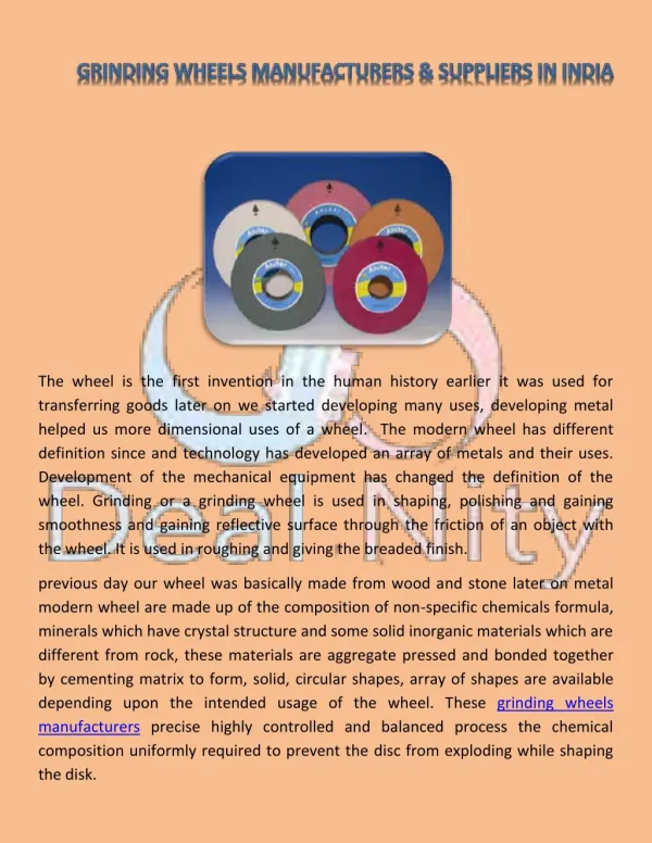
Download
1 / 37
370 likes | 548 Views
NIHON University LEE Lab. Study on elastic characteristics of grinding wheels by means of a grinding wheel model. Takazo Yamada 01/10/2010 Department of Mechanical Engineering, College of Science & Technology, Nihon University. NIHON University LEE Lab. Name : Takazo Yamada

E N D
NIHON University LEE Lab. Study on elastic characteristics of grinding wheels by means of a grinding wheel model Takazo Yamada 01/10/2010 Department of Mechanical Engineering, College of Science & Technology, Nihon University
NIHON University LEE Lab. Name : Takazo Yamada Date of Birth : 1973/1/28 Education : 1992/04-1996/03: Nihon University (Private university) 1996/04-1998/03: Graduate school of Chiba University (National university) Work experience : 1998/04-2001/06: Niigata engineering Co., LTD. (Development and design of machining center) 2001/07-now : Department of Mechanical Engineering, College of Science and Technology, Nihon University
NIHON University LEE Lab. Stiffness of grinding sysem Static Stiffness in Wheel Support System : Ks Stiffness of Grinding Wheel : Kg Grinding Wheels Static Stiffness In Workpiece Support System : Kw Workpiece Schematic model of grinding system Surface grinding machine The stiffness of the grinding wheel support system and the stiffness of the workpiece support system are determined depending on the construction of each grinding machine. On the other hand, the contact stiffness between the grinding wheel and the workpiece varies with a difference in the dressing lead or the grinding condition. Therefore, the quantitative estimation of the contact stiffness is difficult.
Contact Stiffness Kcon Stiffness of Wheels (Deformation of Wheels) Stiffness of Workpiece (Deformation of Workpiece) = + Stiffness of Workpiece The theory of Hertzian Contact Stiffness of Wheels F Flat surface Cylinder Sphere F Sphere Flat surface NIHON University LEE Lab. Background of study Conventional Study of contact condition of grinding wheel, Since grinding wheel consists of abrasive grains and bonds, it is considered that grinding wheel is not uniform body.
NIHON University LEE Lab. Background of study Fracture Expansion High speed rotating High speed rotation Elastic deformation due to centrifugal force Fracture of grinding wheel by the effect of centrifugal forces The safety in machining shops Cutting error A lot of studies have been carried out so far. Under the condition that wheels are assumed to be rotating uniform continuous plate →Theory of rotating circular disk Under the assumption that voids in wheels are cracks in wheels →Theory of Griffith These theoretical methods are inadequate for application to actual estimation of fracture speeds.
NIHON University LEE Lab. Aims In this study, in order to obtain the contact stiffness, expansion of wheel and fracture peripheral speed of wheel, a grinding wheel model was proposed. Contact stiffness Contact force Fracture Expansion Centrifugal force Proposed grinding wheel model
NIHON University LEE Lab. What is the proposed grinding wheel model?
k Spring Pore A √2A Bond Abrasive grain A NIHON University LEE Lab. Proposed grinding wheel model Rigid body Spring Abrasive grain Static Stiffness k ? Bond D Grinding matrix model Base unit of proposed model By arrange this basic unit Stick Wheel
D √2A A A NIHON University LEE Lab. Modelling method of proposed grinding wheel model WA60J6V abrasive grain type Hardness Bond type Grain size G Structure S(Percentage of grain Vg) Distance between successive two grains
A k? A spring model α NIHON University LEE Lab. Calculation method of stiffness of one bond bridge F = Kδ = [k×α]δ Geometrical coefficient Spring constant of single spring element Geometrical coefficient of grinding wheel: α a is a function of angle q. and, in case of combining springs, this relation is the same. So, a is a characteristic value of grinding wheel model.
Y X Z NIHON University LEE Lab. Calculation method of stiffness of one bond bridge In case of that concentrated force 1 N is loaded for Y axis direction, deformations of X and Z axis direction are much smaller than the deformation of Y axis direction. It is known that deformations of X and Z axis direction can be neglected. So, considering only Y axis direction, equation can be changed as follows: Analysis of three point bending test From the analysis of three point bending test for abrasive stick, deformation δ for the certain spring constant k and the certain force F can be obtained. Substituting k, F and δ into this equation, geometrical coefficient α can be calculated. F a can be obtained by FEM software. F d 1 k α= = = δ
F L Load Load W H F d 1 a k = Y X Z NIHON University LEE Lab. Calculation method of stiffness of one bond bridge -Analysis- -Experiment- Geometrical coefficient : a Stiffness ratio : F/d Stiffness of single bond bridge
F 1 a F d d Screw k= Force sensor Abrasive stick PC Electrical micrometer NIHON University LEE Lab. Results of bending test Force F and deflection d can be measured by the three point bending test. Stiffness of single bond bridge Vitrified wheel Grain size #100 (Vg=50%) Resinoid wheel Grain size #100 (Vg=50%)
1 a F d k= d d/2 D/2 1 a F d L k = L/2 D k[N/mm] Stiffness ∥ k Vitrified #120 kv =3.87N/mm NIHON University LEE Lab. Calculated results of stiffness of single bond bridge k Stiffness of single bond bridge decreases with the increase of the grain size. This is caused by the size effect of bond. Stiffness ∥ 2k Vitrified #60 kv =8.01N/mm (a) Case of #60 Relationship between stiffness of single bond bridge k and grain size (b) Case of #120
Size of Grinding Wheels Grinding wheels WA60J6B Symmetric conditions Bond Resinoid bond External diameter f30, f45, f60 Internal diameter f9.5 10mm Width of wheel 2.17N/mm Static stiffness k Restrictions NIHON University LEE Lab. Contact Analysis Condition of analysis with mathematical model Since the wheel is symmetrical around rotating axis, quadrant model is used. Since this model has inherent anisotropy, the analysis is carried out under four contact directions, 0, 15, 30 and 45 degrees.
546 Points 650 Points 702 Points 910 Points 1014 Points 806 Points Node Element NIHON University LEE Lab. Contact Analysis The loads are calculated then balanced to elastic deformation.
Cylinder Sphere F Flat surface Relationship between load and deformation of resinoid wheel NIHON University LEE Lab. Comparison between analyzed results and experimental results
Cylinder Sphere F Flat surface Comparing the experimental results and the theory of Hertzian contact Experimental results are larger than the calculated amounts. The theory of Hertzian contact cannot be applied tothe estimation of the wheel deformations in contact area. Comparing the experimental results and the analytical results proposed in this study Experimental results correlate well with the analytical results. In order to make clear the wheel deformation, the phenomena of each grain has to be considered. NIHON University LEE Lab. Results of experiments and analysis
Expansion High speed rotating NIHON University LEE Lab. Expansion of wheel due to the centrifugal force Elastic deformation due to centrifugal force Cutting error
Y Maximum Proposed model exhibits anisotropy Minimum Z X Maximum f200 Analyzed results NIHON University LEE Lab. Analysis method and analyzed results of expansion of wheel Spindle speed N (N=2800min-1) Rigid body (Mass of grain +Mass of bond) Symmetric conditions Spring element Symmetric conditions Analysis condition
2mm 2mm 2mm 2mm 7.06mm 7.06mm 9.41mm 2.35mm Width of grinding wheel 25mm Width of grinding wheel 25mm • Low rotating speed (250min-1) (b) High rotating speed (2800min-1) • Experimental results of vitrified wheels #60 NIHON University LEE Lab. Measurement method of actual expansion of wheel 250min-1 250min-1 2800min-1 5mm アクリル ①Grinding of flat surface ②Groove for low rotating ③Groove for high rotating
NIHON University LEE Lab. Comparison between analyzed results and experimental results Comparing results from analysis and experiment, it is shown that the maximum amount of analytical results agree with experiment results. Since experiment results were measured by copying to the specimen surfaces, the measured results are obtained maximum expansion amount. So, experimental results agree with the maximum analyzed results. Using proposed grinding wheel model, it is shown that expansion of grinding wheel can be analyzed. Comparison between analyzed results and experimental results
High speed rotation Fracture of grinding wheel by the effect of centrifugal forces The safety in machining shops NIHON University LEE Lab. Fracture peripheral speed analysis by means of grinding wheel model
Rotating speed N Spring element Symmetric condition sr • Rigid body Restricted in Z axis sq Center Y Symmetric condition Fracture Z X NIHON University LEE Lab. Fracture analysis From the theory of rotating circular disk Fracture Internal Maximum force of spring element takes place in this internal area When the force in this area is greater than the fracture force acting in the spring element in the wheel, fracture takes place. • Relation between stress and radius
F h l Maximum stress point (a) Abrasive stick F Stick No. 1 2 3 Width mm 8.0 4.0 5.0 Height mm 5.7 5.7 7.1 Length mm 40 40 40 Maximum force element (b) Analytical model Y X Z NIHON University LEE Lab. Calculation of fracture force acting spring element Pb Fracture force Results of three point bending test Analysis of three points bending test
F Maximum force element (b) Analytical model NIHON University LEE Lab. Calculation of fracture force acting spring element Pb It is known that the fracture force acting spring element Pb decreases with the increase of grain size without any dispersion. It may be considered that since the volume of bond decreases with the decrease of grain diameter, bonds become easier to be broken by smaller forces. The average amount of each test piece is treated as the fracture force acting spring element Pb. Relation between grain size and fracture force acting spring element
Rotating speed N Spring element Symmetric condition • Rigid body Restricted in Z axis Center Y Symmetric condition F Z X Maximum force of spring element takes place in this internal area Maximum force element (b) Analytical model NIHON University LEE Lab. Appling fracture force acting spring element to model Relation between grain size and fracture force acting spring element In the fracture analysis, when the acting force of the spring element in the internal area equals the fracture force acting spring element, the rotating speed for that analysis can be regarded as the fracture speed of the grinding wheel.
NIHON University LEE Lab. Analyzed and experimental results Fracture peripheral speed calculated by the conventional theory is constant . However, analytical results shows that the fracture peripheral speed has a tendency to decrease with the increase of the wheel diameter. Wheel Experimental results agree with analyzed results. Max 35000min-1 Fracture peripheral speed can be estimated analytically. Relation between internal diameter and fracture peripheral speed (#60)
NIHON University LEE Lab. Comparison between results of conventionally reported and analyzed results It is clarified that using the proposed grinding wheels model and three point bending test, for an actual grinding wheel, fracture speed of the wheel can be estimated quantitatively. Fracture test of actual grinding wheel Results of analysis and experiment Analyzed results agree with results of conventionally reported. Three point bending test for stick grinding wheel
Pore 1 a F d k= Spring Bond Abrasive grain 1 a F d k = k[N/mm] NIHON University LEE Lab. Summary Proposed grinding wheel model Stiffness of single bond bridge Proposed model a F/d
Bond Abrasive grain Case of stillness (0 min-1) d F Centrifugal force d F Case of rotation (3000 min-1) NIHON University LEE Lab. Summary Expansion of wheel Contact stiffness Fracture speed Contact stiffness under the rotational state
NIHON University LEE Lab. Thank you for your kind attention!
Expansion High speed rotating 粒度 加工時の砥石の変形 NIHON University LEE Lab. Deformation due to contact and centrifugal forces Contact stiffness Using proposed grinding wheel model Deformation due to centrifugal force Contact deformation of wheel in stationary state
Bond Abrasive grain Case of stillness (0 min-1) d Workpiece F Deformation due to contact force Resinoid wheels #60 fo205, fi50.8 Contact stiffness is high by the centrifugal force Centrifugal force d Case of rotation (3000 min-1) F Deformation due to contact and centrifugal forces f50.8 f205 NIHON University LEE Lab. Deformation due to contact and centrifugal forces Resinoid wheel: A=0.285mm m=3.4x10⁻⁸kg k=2.29e6N/mm Condition of analysis Influence of centrifugal forces to contact stiffness In grinding operation, it is known that elastic deformation of grinding wheel is about 10 percent larger than amount of stationary state.
Vb V Pb P NIHON University LEE Lab. Calculation method of fracture peripheral speed Vb Tangential force sq derived from the theory of rotating circular disk is ra is internal radiusm rb is external radiusm w is angular velocity red/sec u is Poisson’ ratio (u=0.3) r is densitykg/m3 sq=P/A , w =V/rb And similarly, the relation between the fracture force acting spring element Pb and fracture peripheral speed Vb can be shown as follows; From above, fracture peripheral speed Vb is as follow; Fracture force acting spring element Pb have been obtained before. Calculating the force acting spring element P under any peripheral speed V, fracture peripheral speed Vb can be obtained.
Y Z X NIHON University LEE Lab. Fracture analysis From fracture analysis, relation between the force acting spring element and any peripheral speed V (V=6180m/min) is obtained. Peripheral speed V=6180m/min Spring element Symmetric condition • Rigid body Restricted in Z axis Center Symmetric condition Relation between internal diameter and force acting spring element Force acting spring element P Internal External Ratio of internal and external diameter i =
NIHON University LEE Lab. Analyzed and experimental results Relation between internal diameter and fracture peripheral speed (#60)