Download
1 / 32
440 likes | 794 Views
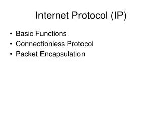
Application. Application. TCP. UDP. ICMP. IP. ARP. RARP. Physical. network. Internet Protocol (IP). ubiquitous communications across heterogeneous networks in any technology any host on the Internet can communicate with any other host via IP packets TCP peers exchange segments

E N D
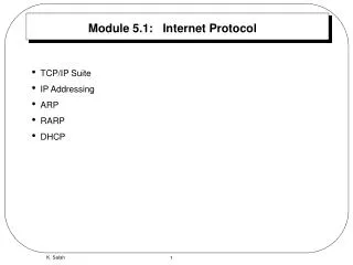
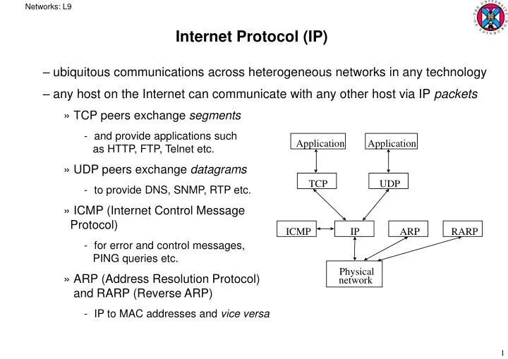
Networks: L9 Application Application TCP UDP ICMP IP ARP RARP Physical network Internet Protocol (IP) • ubiquitous communications across heterogeneous networks in any technology • any host on the Internet can communicate with any other host via IP packets • TCP peers exchange segments • and provide applications such as HTTP, FTP, Telnet etc. • UDP peers exchange datagrams • to provide DNS, SNMP, RTP etc. • ICMP (Internet Control Message Protocol) • for error and control messages, PING queries etc. • ARP (Address Resolution Protocol) and RARP (Reverse ARP) • IP to MAC addresses and vice versa
Networks: L9 Application request • Encapsulation and header information • TCP header contains source anddestination port numbers • IP header contains source anddestination IP addresses, andtransport protocol type • Ethernet header containssource and destinationphysical addresses, andnetwork protocol type • receivers determine which higher level protocol the PDU is intended for from the protocol type in their header • ethernet sends PDU up to IP, ARP, RARP etc. • IP sends to TCP, UDP • TCP to application, based on port number etc. TCP Header IP Header Ethernet Header FCS
Networks: L9 Machine A Machine B Application Application • internet layer provides a best-effort connectionless packet transfer service • packets routed without connection set up • each router determines the next hop for packets • packets routed independently and may traverse different paths • may arrive at destination in any sequence order • intermediate routers may discard packets when congestion occurs • recovery the responsibility of the transport layer • independent of underlying network technology • accommodates segmentation and reassembly if necessary Transport Router/Gateway Transport Internet Internet Internet Network Interface Network Interface Network Interface Network 1 Network 2
Networks: L9 0 4 8 16 19 24 31 • IP Packet structure: • version : IPv4 and migration to IPv6 • IHL : header length • Type of Service : packet priority • bits 0-2 : precedence; bits 3-5 : delay, throughput, reliability • usually ignore by routers • Total Length : length of IP packet including header • Identification, Flags, Offset : used for fragmentation and reassembly Version IHL Type of Service Total Length Identification Flags Fragment Offset Time to Live Protocol Header Checksum Source IP Address Destination IP Address Options (variable length) Padding
Networks: L9 • Time to Live (TTL) : number of seconds packet is allowed to stay in network • usually interpreted as maximum number of hops allowed • each router decrements count by one • if zero reached, packet discarded and ICMP message sent back to source • avoids packets wandering aimlessly around the Internet • Protocol : which protocol handler is to receive the packet at the destination • e.g. ICMP = 1, TCP = 6, EGP (Exterior Gateway Protocol) = 8, UDP = 17 etc. • Header Checksum : packet discarded if checksum fails • data part of packet not checked – left up to higher level protocols • must be recomputed after TTL decremented at each hop • Source IP Address & Destination IP Address : Network ID + Host ID • Options : security level, source routing, timestamp, router alert etc. • source routing : routing information provided by the source • timestamp : can be used for performance monitoring • router alert : extract packet contents at a router and perform processing there • used by RSVP (Reservation Protocol) to request a specific QoS along the route • Padding : to make header a multiple of 32 bytes
Networks: L9 Source Router Destination IP IP Network Network • Fragmentation and Reassembly • each physical link imposes a maximum size of transmission unit (MTU) • e.g. ethernet 1500 bytes, FDDI 4464 bytes • IP may have to break a large packet into smaller fragments to transmit them • each fragment is sent independently, as though it were an IP packet • any router may need to fragment packets to smaller sizes again: • the destination IP is the only entity that reassembles fragments into the original packet
Networks: L9 • to reassemble a packet • destination waits until all the fragments have been received • if any fragment is lost, the whole original packet is abandoned • e.g. due to error or to congestion • lost fragments detected by using a time-out following arrival of first fragment • Identification field in IP header used to identify which packet a fragment belongs to • source must not reuse an identification value for a sufficiently long period • Flag bits : • DF : don’t fragment • if packet is longer than MTU for next hop, discard packet and send error message • MF : more fragments follow this one • Offset field : measures the offset in the packet of this fragment • in units of eight bytes • since field is only 13 bits long; this then allows lengths up to 65536 bytes • performance: • fragment loss means retransmission of all packet fragments again • could be done more efficiently with selective retransmission
Networks: L9 • IP Addressing : • each host assigned a unique 32-bit IP address : • Network ID + Host ID • or multiple IP addresses for hosts with multiple interfaces • Network IDs allocated by RIPE (Réseaux IP Européens) NCC (Network Coordination Centre) in Amsterdam for Europe, Middle East & North Africa • one of three Regional Internet Registries • ARIN (Americas), APNIC (Asia Pacific) • allocation of blocks of IP addresses to Local Internet Registries e.g. ISPs • who further allocate them to their users • Host ID allocated by local network administrator • or dynamically by DHCP • routers only need to route packets on basis of the Network ID part • reduces size of routing tables • Five address classes : A to E • class D used for multicast services to a group of hosts simultaneously • class E reserved for experiments
Networks: L9 Bit position: 0 1 2 3 8 16 31 Class A 0 Net ID Host ID • class A : 7+24 : 126 networks + 16 million hosts; class B 14+16 etc. • host ID = all 1s: broadcast to all hosts of the specific network • IP address = all 1s : packet is broadcast to all hosts on the local network • 127.x.x.x : local loopback i.e. this node – used for testing • host ID = 0 : refers to a network rather than a host • byte-by-byte dotted notation : w.x.y.z • e.g. 129.215.58.7 : (100….) class B : network ID 1.215, host ID 58.7 • e.g. 224.0.0.9 : (1110….) multicast address for RIP-2 routers Class B 1 0 Net ID Host ID Class C 1 1 0 Net ID Host ID Class D 1 1 1 0 Multicast address Class E 1 1 1 1 Reserved for experiments
Networks: L9 • Subnet addressing • class B network addresses have 65534 host Ids • too many to administer easily • instead add another hierarchical level – subnets of the network • the local network administrator can choose the size of the subnet • subnet IDs can be allocated to local LANs within the organisation • the subnet can be identified by and-ing the IP address with a subnet mask • e.g. 255.255.255.0 for a subnet with up to 255 hosts • the packet can then be routed to the correct subnetwork • allows IP addresses to be aggregated by routers • routing tables reduced in size • IP addresses remain two-part outside the organisation • since subnets are invisible externally Original 1 0 Net ID Host ID address Subnetted 1 0 Net ID Subnet ID Host ID address
Networks: L9 • e.g. a packet arrives at router R1 addressed to host H5 at 150.100.15.11 : • if R1 knows subnet mask of 255.255.255.128 is in use • subnet address of packet is 150.100.15.0 • assuming this address is in R1’s routing table, it can forward the packet to R2 • R2 does the same and discovers the subnet is on one of its network interfaces • it can therefore send the packet straight to H5 H1 H2 150.100.12.154 150.100.12.176 150.100.12.128 150.100.12.129 150.100.0.1 R1 To the rest of H3 H4 150.100.12.4 the Internet 150.100.12.55 150.100.12.24 150.100.12.0 150.100.12.1 R2 H5 150.100.15.54 150.100.15.11 150.100.15.0
Networks: L9 • IP Routing of packets • originating host checks the destination IP address in its routing table • to see if it is to a directly connected host • if so, the packet sent directly to its destination, over local LAN etc. • otherwise, routing table will indicate the packet be sent to a router • probably a default router directly connected to the host • when router receives the packet, it checks whether it is destined for itself • if so, it is delivered to the higher level protocol • if not, it determines the next-hop router and network interface • routing table entry contents : • IP address of next-hop router • flags : • H (network=0; host=1) • G (direct=0; router=1) • network interface address and type
Networks: L9 • Four steps in attempting to deliver the packet : • step 1: table searched for the complete IP address • if so, forwarded according to next-hop and G flag entries • step 2 : table searched for destination network ID • if so, packet forwarded according to next-hop and G flag entries • step 3 : table searched for a default router entry • if so, packet routed to it • step 4 : if none of the searches are successful • packet is declared undeliverable • an ICMP “host unreachable” error packet sent back to originating host
Networks: L9 • example: host H5 wishes to send a packet to host H2 • H5’s routing table : • 1 : loopback; H=1 indicates a Host • 2 : default router (G=1); next-hop R2 • 3 : to a network address (H=0) with a direct connection (G=0) • H5 searches table for 150.100.12.176 (H2) • not in, so searches for the destination network ID 150.100.12.128 • assuming a subnet mask of 255.255.255.128 • not in, so finds default router R2 • and forwards the packet to it
Networks: L9 • R2’s routing table: • R2 searches its routing table in the same way • and forwards packet to router R1 • R1’s routing table: • R1 searches its table for 150.100.12.176 and finds a match • so sends the packet through interface eth1 to H2
Networks: L9 • e.g. routing table from a Windows 2000 machine • using command : route PRINT =========================================================================== Interface List 0x1 ........................... MS TCP Loopback interface 0x2 ...00 a0 c9 a4 9d 18 ...... Intel(R) PRO PCI Adapter =========================================================================== =========================================================================== Active Routes: Network Destination Netmask Gateway Interface Metric 0.0.0.0 0.0.0.0 129.215.58.108 129.215.58.7 1 0.0.0.0 0.0.0.0 129.215.58.109 129.215.58.7 1 127.0.0.0 255.0.0.0 127.0.0.1 127.0.0.1 1 129.215.58.0 255.255.255.0 129.215.58.7 129.215.58.7 1 129.215.58.7 255.255.255.255 127.0.0.1 127.0.0.1 1 129.215.255.255 255.255.255.255 129.215.58.7 129.215.58.7 1 224.0.0.0 224.0.0.0 129.215.58.7 129.215.58.7 1 255.255.255.255 255.255.255.255 129.215.58.7 129.215.58.7 1 Default Gateway: 129.215.58.109 =========================================================================== Persistent Routes: None
Networks: L9 • Address Resolution Protocol (ARP) • to find the Medium Access Control (MAC) ethernet address of a host • e.g. H1 (150.100.76.20) wants to find MAC address of H3 (150.100.76.22) • H1 first checks its ARP cache for H3’s IP address • if not in, H1 broadcasts an ethernet frame requesting the MAC address corresponding to the IP address 150.100.76.22 • arp message contains IP and MAC addresses of H1, as well as IP address of H3 • each host on the network receives the ARP request • checks for a match with its own IP address • if no match, the ARP request is discarded H1 H2 H3 H4 150.100.76.23 150.100.76.22 150.100.76.20 150.100.76.21 ARP request : what is the MAC address of 150.100.76.22 ? protocol type x806 protocol type for IP packets is x800 ethernet header ARP message padding ethernet CRC
Networks: L9 • when H3 finds a match : • H3 adds H1’s IP address/MAC address to its own ARP cache • H3 sends an ARP reply containing its MAC address back to H1 alone • when H1 receives the ARP reply message from H3, it updates its cache • and can send IP packets to H3 via ethernet • e.g. ARP cache on a Windows 2000 machine : • using command : arp -a H1 H2 H3 H4 ARP response : my MAC address is 08-00-5A-C5-3B-94 Interface: 129.215.58.7 on Interface 0x2 Internet Address Physical Address Type 129.215.58.109 08-00-20-ad-9f-12 dynamic
Networks: L9 • Reverse Address Resolution protocol • for a host to get its own IP address when it just knows its MAC address • e.g. on thin clients of a server • host broadcasts a RARP request containing its MAC address • a server which knows replies by sending a RARP response containing the requested IP address • server must be located on same physical network as the host
Networks: L9 • Problems with IPv4 • running out of IP addresses • due to unexpectedly fast growth of the Internet • inefficient use of 32-bit IP address space • addresses allocated in blocks at a time • large blocks may be under-utilised e.g. class A address space • difficulties in scaling routers to deal with vast number of Internet addresses • lack of IP addresses ameliorated by use of Network Address Translation (NAT) • router problems ameliorated by use of Classless Interdomain Routing (CIDR) • together these have substantially postponed the need to move to IPv6 • other problems: • possible corruption of dynamically allocated leased IP addresses (DHCP) • limited flow control – need to control different types of flow independently • security and encryption lacking – to facilitate use of Virtual Private Networks
Networks: L9 • Network Address Translation • reducing the real Internet to a relatively small number of hosts • and using these hosts as gateways into sub-internetworks • IP addresses can be re-used in separate internal sub-internetworks • each internal sub-network lives behind a NAT-enabled gateway/router • registered IP addresses used outside the gateway to connect to public network • assigned by the usual authorities as normal • a set of unregistered IP addresses is used in the private local network • a range of addresses are set aside for this re-use by the authority • hosts on the local network communicate using local unregistered addresses • packets outgoing to the public network have their local IP addresses translated to registered external IP addresses by the gateway and vice versa
Networks: L9 • Static NAT: • mapping an unregistered IP address to a registered IP address one-to-one • useful when a device needs to be accessible from the public network • relies on not all local hosts needing connections all the time • Dynamic NAT: • maps an unregistered IP address to a registered IP address from a group of registered IP addresses as and when required
Networks: L9 • example: • a local network host attempts to connect to an external host • router receives the packet from the local host • router replaces sending host’s IP address with first available IP address from its set of registered IP addresses • router saves the host’s local IP address and its replaced external IP address in an address translation table • when a packet comes back from the destination host, router checks the destination IP address on the packet • looks in its address translation table for a match • if no match, the packet is discarded • replaces the external IP address with the local IP address • forwards the packet on the local network to the local host • local host receives the packet • process repeats as long as the local host is communicating with the external host • then the external IP address reclaimed for use by another local host • after a suitable time-out limit of non-use
Networks: L9 • Overloading: • maps unregistered IP addresses to a single registered IP address by using different ports (also known as Port Address Translation (PAT)) • example: • a local network host attempts to connect to an external host • router receives the packet from the local host • router replaces sending host’s IP address with the router’s external IP address • and also replaces the sending host’s source port with a port number that can be used to index into its address translation table • router saves the host’s local IP address and its internal port number in its address translation table • in the external port number position of the table • together with the external IP address of the router • and the destination host’s IP address
Networks: L9 • when a packet returns from the destination external host • router checks destination port on the packet • looks in its address translation table to see which local host it is for • and also checks that packet is from the valid external host for this connection • changes the destination address and port to the ones saved in the table • and sends the packet to the local host • can be combined with a dynamic allocation system if required • NAT automatically creates a firewall between the local network and outside • only allows connections which originate from within the local network • though static inbound mapping is also possible and may be allowed • the gateway can also provide filtering and traffic logging
Networks: L9 • Classless Interdomain Routing (CIDR) • lifts the restriction on IP address classes A, B, C etc. • an arbitrary prefix length indicates the network number • e.g. 129.123.0.1/22 indicates a prefix of 22 bits • i.e. a net mask of 255.255.252.0 • CIDR routers route packets according to the higher-order bits of the IP address • CIDR routing table entries contain the 32-bit IP address and a 32-bit mask • and-ed together to produce an address to search for in its routing table • a single entry in the routing table covers a block of useful IP addresses • address aggregation for IP addresses which follow the same route • known as supernetting • requires that a longest prefix match search scheme be used • IP addresses have to be allocated using policies to capitalise on this capability • e.g. reflecting the physical hierarchical topology of the network • continents use a short prefix, countries slightly longer etc. • masks passed around routers by routing protocol messages e.g. RIP-2 • can significantly reduce the growth of routing table size
Networks: L9 • IP version 6 • to address shortcomings of IPv4 and emerging applications • designed to interoperate with IPv4 during transition period • since 1994 so far! • Longer addresses – 128 bits • Simpler header format e.g. no header length or fragmentation fields • Options provided by more flexible extension headers • Flow label capability to identify a packet flow that needs certain QoS • Security : supports authentication and confidentiality • Large packets : jumbo packets longer than 64Kb • Fragmentation at source only : intermediate routers not allowed to fragment • No checksum field • physical layers perform checksum • higher layers also checksum • so not needed
Networks: L9 0 4 12 16 24 31 Version Traffic Class Flow Label Payload Length Next Header Hop Limit Source Address Destination Address • IPv6 Header format: • version : 6 for IPv6 • traffic class : priority of packet; zero means best-effort • intended to support differentiated services – still experimental • flow label : source desires special handling of this flow of packets • assigned by the source pseudo-randomly • flow requirements specified by a control protocol or within the packets • also still experimental • payload length : length of data excluding the header
Networks: L9 • next header : link to next extension header • hop limit : replaces TTL field in IPv4 • now means what it says! • source and destination addresses : 128 bits • Address Types • Unicast : denote a single host – the normal understanding of IP address • Multicast : a multicast enabled host can join a multicast address group • all IP datagrams to this address get delivered to all group members hosts • a group member informs its local router of its membership of a group • using the Internet Group Management Protocol (IGMP) • datagrams sent along distribution tree branches to group members • packets only need to be replicated at branches in the distribution tree • multicast routing protocols used for distribution • initially flooding from the source • followed by pruning unused branches and possible grafting re-used branches • e.g. Distance Vector Multicast Routing Protocol (DVMRP) • potentially saves considerable bandwidth • was also available in IPv4 but much bigger address space for group Ids • IPv6 address range with prefix xFF
Networks: L9 • Anycast : like multicast with groups of hosts • but only one host gets the packet – typically the closest host • used to enable redundant routers to the Internet • e.g. an organisation with more than one router connected to the Internet • assign the same anycast address to each of these routers • anycast traffic goes to just one of the routers • and into the local network • if the router was to go down, the anycast system automatically redirects traffic via another router into the local network • the IP network is therefore much more robust • anycast addresses are unicast addresses assigned to more than one host • but the hosts must be configured to know the address is a unicast address • IPv6 must be backwards compatible with IPv4 to be interoperable • e.g. IPv4-compatible IPv6 addresses: • 96 bits of zeroes followed by 32 bits of IPv4 address • allows tunnelling of IPv6 traffic across an IPv4 network • hierarchical provider-based i.e. ISP, unicast addresses : n bits m bits o bits p bits (125-m-n-o-p) bits 010 Registry ID Provider ID Subscriber ID Subnet ID Interface ID
Networks: L9 Basic header Routing header Fragment header Authentication header Next header = Next header = Next header = Next header = TCP segment routing fragment authentication TCP Basic header Next header = TCP segment TCP • Extension Headers • an arbitrary number of daisy-chained headers to provide extra options • the basic header has a type field potentially for an interposed extra header • each subsequent header likewise: • or just a single TCP segment: • header types include: • large jumbo packet sizes up to 32-bits worth: • fragmentation header: 0 8 16 24 31 Opt Len = 4 194 Next Header 0 Jumbo Payload Length 0 8 16 29 31 Next Header Reserved Fragment Offset Res M Identification
Networks: L9 • source routing i.e. the sequence of routers to be visited by each packet • segment left : number of route hops remaining • strict mask : whether route is strict for this hop or not 0 8 16 24 31 Next Header Header Length Routing Type = 0 Segment Left Reserved Strict/Loose Bit Mask Address 1 Address 2 . . . Address 24