Download
1 / 31
310 likes | 393 Views
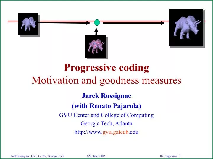
Progressive coding Motivation and goodness measures. Jarek Rossignac (with Renato Pajarola) GVU Center and College of Computing Georgia Tech, Atlanta http://www. gvu.gatech .edu. Progressive refinements. Previously covered connectivity compression is loss-less

E N D
Progressive codingMotivation and goodness measures Jarek Rossignac (with Renato Pajarola) GVU Center and College of Computing Georgia Tech, Atlanta http://www.gvu.gatech.edu
Progressive refinements • Previously covered connectivity compression is loss-less • It is complemented by the compression of vertex data • 3D coordinates, normals, colors, texture coordinates • Discussed later in the “Geometry” section • Exploiting a lossy quantization • When these two are insufficient, we can simplify the model • Reduce triangle and vertex count through a sequence of edge-collapses • Select sequence that minimizes the resulting (geometric or visual) error • We can use progressive transmission that increases accuracy • Download compressed crude model first • When more accuracy is needed, download upgrades and refine model • You may start navigation right away using crude model • Often you may not need to download the complete model at all
? Mesh refinement
B C A D E Just-in-time upgrades of features • Download geometry only when images won’t do • Subdivide surface into features (hierarchical) • Use approximations of feature when acceptable • Replace by more detailed sub-features as necessary • To upgrade a feature, given its boundary, we must construct: • A detailed representation of its (approximate) shape • A partition of the feature’s surface into sub-features
Selective download of feature upgrades Upgrade Geometry Cost Quality Children 0 g0 a0,r0 p0,e0 1,2,3 1 g1 a1,r1 p1,e1 4,5,6 2 g2 a2,r2 p2,e2 7,8,9 User Server view&model manipulation Downloaded upgrades 0,2,3,8,9,10,11,12 Client crude model (g0) 1 3 2 12 9 10 6 7 4 8 11 5 detailed features
Simultaneous access to remote datasets 3D Servers Client viewers Compressed crude models and upgrades
Simplification 1 Simplification 2 Compression Compression Compression upgrade 1 Crude model upgrade 2 Decompression Decompression Decompression upgrade upgrade Compressed successive upgrades
Connected subset of the boundary Surface patch Entire surface Defined by hierarchical simplification Assume its boundary is given Outer loops of a connected patch One triangle of a solids boundary Represent how to stretch the surface between this boundary Compression: bit-efficient model of the internal shape ? What is a good feature for selective upgrade? ? ? ?
Upgrade = reverse simplification compress Upgrade decompress ?
Time to first picture Midway accuracy Time to full accuracy Better Evaluating progressive transmission Error for the received model Bits transmitted (or time)
complete model Non-progressive transmission approximation error bits (time) nothing
single resolution model crude model complete model Two-step approach: Crude-Full approximation error bits (time) nothing
single resolution model two-shot approach crude intermediate complete Multiple levels of accuracy approximation error Longer wait for complete model bits (time) nothing
Want smallest area? crude model final model Optimal, continuous refinement approximation error bits (time)
Simplification Reduce the number of triangles that represent a 3D “feature” Compression Reduce the number of bits needed to represent the “feature” Upgrade Information used to recover an original feature from its simplification Progressive representation Coarse model and a tree of recursive upgrades B C A D E Simplification, Compression & Upgrades
Progressive codingCompressed Progressive Meshes Jarek Rossignac (with Renato Pajarola) GVU Center and College of Computing Georgia Tech, Atlanta http://www.gvu.gatech.edu
Problem of compressing updates • Location • where does a refinement occur • Incidence • how to update the mesh connectivity • Geometry • new coordinates location incidence compressed format
M0 M1 Mmax-1 Mmax ... vsplit vsplit Progressive meshes (Hoppe96) • Simple simplification and refinement operators • edge collapse operation (ecol) • vertex split operation (vsplit) • defined by split-vertex and cut-edges • Series of meshes • defined by crude base mesh M0and sequence of vsplits cut-edges ecol vsplit split-vertex
The inverse of an edge collapse Insert two triangles Cut mesh at 2 adjacent edges Replicates 2 edges and 1 vertex Move new vertex to create gap Fill the crack with 2 new triangles Specify position of new vertex Encode relative displacement (arrow) Incidence cost: 8–13 b/T Identify a vertex (10<log|V|<20) bits Identify 2 incident edges (6 bits?) Vertex splits (Hoppe)
Example not marked marked mesh incidenceupdates CPM (Pajarola&Rossignac 99) • Sequences of vertex splits (as in Hoppe’s PM) • Grouped in batches
Mi Mi+1 {vsplits} {vsplits} 2 j d c f h 1 k CPM encoding of connectivity • Avoid log(V) cost by marking all vertices • 1 bit per vertex in batch • 30% to 50% vertices are split in each batch • Better encoding of cut-edges • log(6)+log(2) • Amortized total connectivity cost 3.6T bits • 1.5 b/T for marking vertices (amortized) • 2.1 b/T for identifying cut edges • Pajarola&Rossignac, Compressed Progressive Meshes, IEEE TVCG’99
CPM butterfly prediction • Predict geometry based on previous LOD • approximation using weighted sum of incident vertices and subset of topology 2 neighbors
v’ B’ A’ A v B CPM prediction error encoding • Estimate edge collapse • predict original vertices A’, B’ • predicted edge collapse vector v’ • prediction error e = v’ - v • CPM collapses edge to its mid-point • Encode prediction error • Laplace distribution L(x) • based on prediction error variance of current refinement batch • create corresponding Huffman encoding for e
Total amortized cost per triangle • Bunny • 9666 triangles, 10 LODs, 11.3T bits (3.6 connectivity + 7.7 geometry) • Horse • 21622 triangles, 9 LODs, 10.6T bits (3.5 + 7.1) • Skull • 21904 triangles, 7 LODs, 10.9T bits (3.4 + 7.5) • Fohe • 7240 triangles, 7 LODs, 13.7T bits (3.5 + 10.1) • Fandisk • 12950 triangles, 9 LODs, 11.4T bits (3.7 + 7.7)
PFS 254% • Estimated at 18T bits, fewer LODs Comparison with TS and PFS 2832 vertices approximation error TS [Taubin, Rossignac 98] PFS [Taubin et al. 98]CPM [Pajarola, Rossignac 99] bits crude initial model TS 100% CPM 125%
Error protection for CPM G. Al-Regib, Y. Altunbasak and J. Rossignac. “An Unequal Error Protection Method for Progressively Compressed 3-D Meshes”, Int. Conf. on Acoustics, Speech and Signal Processing (ICASSP). May 2002. • Add error correction channel bits to increase the chances of recovering from transmission errors • Adjust level of error protection to the importance of the refinement batch (optimization)
Progressive Transmission of Tetrahedral MeshesImplant-Spray Jarek Rossignac (with Renato Pajarola and Andrzej Szymczak) GVU Center and College of Computing Georgia Tech, Atlanta http://www.gvu.gatech.edu
cut-faces ecol vsplit split-vertex Progressive Tetrahedral Meshes ImplantSpray: Pajarola&Rossignac&Szymczak, IEEE VIS’99 • Vertex split refinement operator • Extension of vertex split for triangle meshes [Staadt&Gross98] • Defined by split-vertex and set of incident cut-faces • Series of tetrahedral meshes defined by sequence of vertex-splits • Send crude model and batches of refinement updates • Mark split-vertices • Encode cut-faces
Identifying cut-faces for the split-vertex • A vertex has roughly • 12 incident edges • 30 incident triangular faces • 20 incident tetrahedra • A split-vertex has about 6 cut-faces • We must select about 6 triangular faces out of 30 • Hull: The boundary of the star of the split-vertex • A manifold surface • Skirt: Cut-faces • connected surface around split-vertex • The skirt boundary • a cycle of k edges in the hull • closed path on planar triangle graph cut-faces split-vertex hull skirt
Results of Progressive Tetrahedral Meshes • Turbine blades • blades and exterior as tetrahedral mesh • 576576 tetrahedra • 49 LODs • 5.02 bits per tetrahedron • connectivity information • no geometry data • Compare to indexed face list: • 4x17 bits per tetrahedron