Download
1 / 52
520 likes | 750 Views
0. System ID with relay 1. Strike point for high elongation Add upper strike control Coordinate with squareness 2. X-point with strike MIMO (add off diagonal) XMP Add I to PF3 Add D to PF2 To strike point Integral Fix Plasma models CREATE-L France DINA Moscow CORSICA LLML TSC PPPL.

E N D
0. System ID with relay 1. Strike point for high elongation • Add upper strike control • Coordinate with squareness 2. X-point with strike MIMO (add off diagonal) • XMP • Add I to PF3 • Add D to PF2 • To strike point • Integral Fix • Plasma models • CREATE-L France • DINA Moscow • CORSICA LLML • TSC PPPL
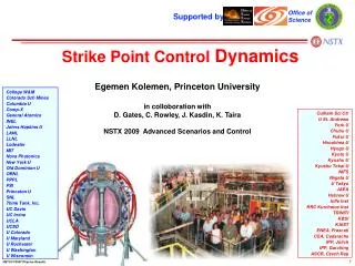
NSTX Supported by Implementation, Testing and Tuning of the Squareness Control with PF4 College W&M Columbia U Comp-X General Atomics INEL Johns Hopkins U LANL LLNL Lodestar MIT Nova Photonics New York U Old Dominion U ORNL PPPL PSI Princeton U Purdue U SNL Think Tank, Inc. UC Davis UC Irvine UCLA UCSD U Colorado U Maryland U Rochester U Washington U Wisconsin Culham Sci Ctr U St. Andrews York U Chubu U Fukui U Hiroshima U Hyogo U Kyoto U Kyushu U Kyushu Tokai U NIFS Niigata U U Tokyo JAEA Hebrew U Ioffe Inst RRC Kurchatov Inst TRINITI KBSI KAIST POSTECH ASIPP ENEA, Frascati CEA, Cadarache IPP, Jülich IPP, Garching ASCR, Czech Rep U Quebec Egemen “Ege” Kolemen, S. Gerhardt, D. Gates 2009 NSTX Research Day, ASC Room B-318 December 2nd, 2009
Title: Implementation, Testing and Tuning of the Squareness Control with PF4 Group: Advanced Scenarios and ControlSubmitted By: E.Kolemen, S. Gerhadt, D. GatesAffiliation: ASC, NSTX, PPPLEmail: ekolemen@pppl.govMilestone: -ITPA: -Brief Description:We propose to control squareness and the boundary shape via PF4 coils. Experiment proposal consist of System Identification of the squareness change to variation in PF4/PF5 coil and developing a PID controller for squareness.Background:This year there will be an upgrade to the coil protection hardware and modifications to PCS which will turn on PF4 coils. This will give us the opportunity to incorporate real time PF4 coil inputs in the control algorithm. We propose to control squareness and the boundary shape via PF4 coils.Experimental Approach/Plan:Experimental Plan Consists of:1.System Id: We will first need to identify the effect of these coils on the boundary shape. This will be done with the new relay feedback system identification capability that will be available this year in PCS.2.Control Algorithm Implementation and Tuning: Control theory will be used to find the optimal way of controlling squareness. PF4 and PF5 coils are very close to each other and we expect that there will be coupling between the effect of these coils. A multi-input, multi-output (MIMO) algorithm for squareness may be needed. Also, inner and outer strike points will be controlled in real time this coming year which will put PF1 and PF2 coils in use. This will be the first time all the coils will be working in a feedback loop. There is a strong possibility of the cross coupling between these control loops will lead to instabilities or at least reduce performance of these coils. This will be have to be looked at and maybe a change in the control loops will be implemented. The controller will be tested and tuned experimentally.Machine Time Requested (run days):1-2 daysMinimum Useful Machine Time (run days):1 daySpecialRequirementsOperations/Development:Yes. We will need to adjust the Isoflux gains and test the harware/software coil protections for PF4 and PF5.Diagnostics:Analysis: Squareness Optimization May Enable Radiated Power Control
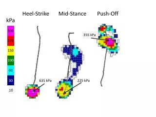
LLD will Lead to Increasing Radiated Power • Monotonous increase in Prad, radiated power. (Plasma Phys. Control. Fusion 51 (2009) 124054 M G Bell et al.) • Due to increase in the radiation from impurities (Iron/Carbon emissions) Fig. 7.17.2 Discharges with and without ELMs, showing the increase in electron density and impurity accumulation associated with the ELM-free case. Note that the iron emission line signals are amplified in the case with ELMs (ASDEX Team, Nuclear Fusion 29, 1959 A989))
Induce ELMs to Take the Impurities Out • Induce ELMs to get rid of the impurities • What are the free shape parameters we have to change the instability boundary? • Triangularity (X) • Elongation (X) • This year PF4 control we enable Squareness! Squarness control with PF4 coils
Effect of Squareness on Stability • In support of the view that edge second stability access allows ~ > a~~~ are experiments in which the plasma ‘squareness’ was varied [18]. In these experiments a sudden transition to small high frequency ELMs was observed at very high and very low squareness where simulations [1] predicted edge current density significantly exceeding the collisionless bootstrap current would be required for access to second stability [Fig. 2(a)]. This qualitative change in ELM character occurred over a narrow range in squareness and as such is unlikely to be the result of a change in fueling efficiency or impurity influx. At the transition to small ELMs the edge pressure gradient is observed to drop to the calculated first stable limit. Additional gas puffing in discharges which would otherwise have large ELMs but which are close to the small ELM shape produced a transition to small ELMs consistent with a decrease in edge bootstrap current with increased collisionality. • The Effect of Plasma Shape onH-mode Pedestal Characteristics on DIII-D,T. H. Osborne • Pedestal Performance Dependence Upon Plasma Shape, A. W. Leonard Low : ne reduced by 50%
Squareness Optimization May Enable Radiated Power Control • LLD will likely lead to monotonous increase in radiated power due to increase in the radiation from impurities (Iron/Carbon emissions) • Plasma Phys. Control. Fusion 51 (2009) 124054 M G Bell et al. • ASDEX Team, Nuclear Fusion 29, 1959 A989 • Need ELMs to get rid of the impurities and thus radiated power. • Most of the shape parameters (such as δ and κ) are fixed for the shots • This year we will include squareness control. • Upgrade to the coil protection hardware • Modifications to PCS and correct gains in Isoflux control • Squareness changes the pedestal stability boundary and may effect the ELMs • The Effect of Plasma Shape on H-mode Pedestal Characteristics on DIII-D, T. H. Osborne • Pedestal Performance Dependence Upon Plasma Shape, A. W. Leonard • Squareness optimization and studying the stability as squareness varies will be useful for this years shots with LLD.
NSTX Supported by Development of Fiducial Shots with LLD: Strike Point Control Improvement and Incorporation in Regular Operation College W&M Columbia U Comp-X General Atomics INEL Johns Hopkins U LANL LLNL Lodestar MIT Nova Photonics New York U Old Dominion U ORNL PPPL PSI Princeton U Purdue U SNL Think Tank, Inc. UC Davis UC Irvine UCLA UCSD U Colorado U Maryland U Rochester U Washington U Wisconsin Culham Sci Ctr U St. Andrews York U Chubu U Fukui U Hiroshima U Hyogo U Kyoto U Kyushu U Kyushu Tokai U NIFS Niigata U U Tokyo JAEA Hebrew U Ioffe Inst RRC Kurchatov Inst TRINITI KBSI KAIST POSTECH ASIPP ENEA, Frascati CEA, Cadarache IPP, Jülich IPP, Garching ASCR, Czech Rep U Quebec Egemen “Ege” Kolemen, S. Gerhardt, D. Gates 2009 NSTX Research Day, ASC Room B-318 December 2nd, 2009
Title: Development of Fiducial Shots with LLD: Strike Point Control Improvement and Incorporation in Regular OperationGroup: Advanced Scenarios and ControlSubmitted By: E. Kolemen, S. Gerhadt, D. GatesAffiliation: ASC, NSTX, PPPLEmail: ekolemen@pppl.govMilestone: -ITPA: -Brief Description:This year NSTX will need a new fiducial shot development due to the new restrictions and requirements due to LLD installation. One of the most important changes to fiducial is incorporation of the strike point control as part of the regular operation.Background:Last year inner and outer strike point controllers were implemented with the intention of using these controllers with the NSTX upgraded with LLD. While these controllers are operational, there is room for improvement of the performance by adding derivative gains and smoothing the transient phase of these shots. Also these controllers have been used in several experiments but they are still not part of the regular run. We propose to improve the strike point controllers and incorporate them in fiducial shots. Experimental Approach/Plan:We propose to improve the strike point controllers and incorporate them in fudicial shots. We propose:1.Improve control: We will be adding derivative gain and tuning the controllers for better performance2.Improve transient phase: We will study and tune the start phase to avoid the plasma touching the lower plasma boundary. 3.Add upper strike point controllers: Currently, the strike point controllers work only for the lower side, we will implement the upper strike point controller in PCS.Machine Time Requested (run days):1 dayMinimum Useful Machine Time (run days):1/2 daySpecialRequirementsOperations/Development:Diagnostics:Analysis: Squareness Optimization May Enable Radiated Power Control
In support of the view that edge second stability access allows ~ > a~~~ are experiments in which the plasma ‘squareness’ was varied [18]. In these experiments a sudden transition to small high frequency ELMs was observed at very high and very low squareness where simulations [1] predicted edge current density significantly exceeding the collisionless bootstrap current would be required for access to second stability [Fig. 2(a)]. This qualitative change in ELM character occurred over a narrow range in squareness and as such is unlikely to be the result of a change in fueling efficiency or impurity influx. At the transition to small ELMs the edge pressure gradient is observed to drop to the calculated first stable limit. Additional gas puffing in discharges which would otherwise have large ELMs but which are close to the small ELM shape produced a transition to small ELMs consistent with a decrease in edge bootstrap current with increased collisionality. THE EFFECT OF PLASMA SHAPE ON H-MODE PEDESTAL CHARACTERISTICS ON DIII-D Osborne et al.
Using ISolver showed that • The outer strike point predominantly depend on PF2 . • Analyzed the effect of PF2L in ISolver. • The dynamics of Single Input Single Output (PF2L current to Strike Point change) can be modeled as a first order system with time delay. Preliminary Study: ISolver Analysis Strike Point Position versus PF2L PF2L=0 kAmp PF2L=16 kAmp PF2L=8 kAmp • The change in the strike point with different PF2L current
For this system of First Order ODE with time lag we can model it using these constants L = lag in time response ΔCp (%) = the percentage change in output signal in response to the initial step disturbance T = the time taken for this change to occur N = ; where N is the reaction rate Given these we define Experiment Analysis: Step Response and PID Controller P PF2
The point of “tuning” a PID loop is to adjust how aggressively the controller reacts to errors between the measured process variable and desired setpoint. If the controlled process happens to be relatively sluggish, the PID algorithm can be configured to take immediate and dramatic actions whenever a random disturbance changes the process variable or an operator changes the setpoint. Conversely, if the process is particularly sensitive to the actuators that the controller is using to manipulate the process variable, then the PID algorithm must apply more conservative corrective efforts over a longer period. The essence of loop tuning is identifying just how dramatically the process reacts to the controller’s efforts and how aggressive the PID algorithm can afford to be as it tries to eliminate errors. Ziegler and Nichols developed a heuristic sub-optimal but robust first guess for PID controller gains for a 1st order ODE with time lag, based on their expertise in the controls: Experiment Analysis: Step Response and PID Controller
Calculated PID controller P: 170 – 550 (mean 360) P-I has 1-2 ratio I: 340 – 1100 (mean 720) Experiment Analysis: Step Response and PID Controller
Shot 133886: Calculated PID controller P: 170 – 550 (mean 360) P-I has 1-2 ratio I: 340 – 1100 (mean 720) Tuned these values in experiment to P: 400 and I: 800. Results: PID Controller Performance
The outer-strike point controller kept the controller at requested position but problems during the transition During the transient phase of the discharge, equilibrium bifurcated to a nearby solution with a low X-point. Algorithm was jumping from one solution to the other one. To make more stable plasma: Added inner strike point controller. Inner Strike Point Control X-points bifurcation Flux error between real and requested strike point, 134986 (<1mW) Flux Error (webers/rad) Segment to control inner strike point
Shot 133886: Calculated PID controller P: 170 – 550 (mean 360) P-I has 1-2 ratio I: 340 – 1100 (mean 720) Tuned these values in experiment to P: 400 and I: 800. Results: PID Controller Performance std(ideseg13- smooth(ideseg13,11)) % 4.1956e-004 mean(ideseg13- smooth(ideseg13,11)) %-4.5825e-007
Shot 133886: Calculated PID controller P: 170 – 550 (mean 360) P-I has 1-2 ratio I: 340 – 1100 (mean 720) Tuned these values in experiment to P: 400 and I: 800. Results: PID Controller Performance
Strike Point (SP) Control with LLD Operations • Density reduction depends on proximity of outer SP to LLD. • To achieve better and consistent density reduction, and to avoid contact with the LLD and CHI gap, SP needs to be closely controlled. • System ID to develop a First-Order ODE with dead-time model for the strike point motion due to change in PF current: with K= 2.4e-6, T = 9.9 and L = 6.0. • PI controller gains are tuned using Ziegler and Nichols method to Kp=400, KI=800 for outer strike, and Kp=5000, KI=5000 for inner strike point. Left: High , ne reduced by 25% Right: Low , ne reduced by 50% PF1AL PF2L PF2L controls outer SP in red segments. PF1AL controls inner SP in the blue segment.
System ID to develop a First-Order ODE with dead-time model for the strike point motion due change in PF current. • PI controller gains are tuned using Ziegler and Nichols to [400, 800] for outer strike point and [5000, 5000] for inner strike point. Inner/Outer Strike Point Control PF1AL PF2L PF2L controls outer SP in red segments. PF1AL controls inner SP in the blue segment. Outer Strike Point Control flux error is controlled <1mW/rad and position to within <1 cm.
System ID to develop a First-Order ODE with dead-time model for the strike point motion due change in PF current. • PI controller gains are tuned using Ziegler and Nichols to [400, 800] for outer strike point and [5000, 5000] for inner strike point. Inner/Outer Strike Point Control PF1AL PF2L PF2L controls outer SP in red segments. PF1AL controls inner SP in the blue segment. Outer Strike Point Control flux error is controlled <1mW/rad and position to within <1 cm.
Results: PID Controller Performance Outer Strike Point Control flux error is controlled <1mW/rad and position to within <1 cm. Inner Strike Point Control flux error is controlled <1mW/rad. Position is kept to within <1cm. Reconstructions by EFIT is suspected for the bias error.
NSTX Supported by Combined X-point Height and Strike Point Control College W&M Columbia U Comp-X General Atomics INEL Johns Hopkins U LANL LLNL Lodestar MIT Nova Photonics New York U Old Dominion U ORNL PPPL PSI Princeton U Purdue U SNL Think Tank, Inc. UC Davis UC Irvine UCLA UCSD U Colorado U Maryland U Rochester U Washington U Wisconsin Culham Sci Ctr U St. Andrews York U Chubu U Fukui U Hiroshima U Hyogo U Kyoto U Kyushu U Kyushu Tokai U NIFS Niigata U U Tokyo JAEA Hebrew U Ioffe Inst RRC Kurchatov Inst TRINITI KBSI KAIST POSTECH ASIPP ENEA, Frascati CEA, Cadarache IPP, Jülich IPP, Garching ASCR, Czech Rep U Quebec Egemen “Ege” Kolemen, S. Gerhardt, D. Gates 2009 NSTX Research Day, ASC Room B-318 December 2nd, 2009
Title: Combined X-point Height and Strike Point Control Group: Advanced Scenarios and ControlSubmitted By: E. Kolemen, D. Gates, S. GerhardtAffiliation: ASC, NSTX, PPPLEmail: ekolemen@pppl.govMilestone: -ITPA: -Brief Description:During the transient phase of the shots with the outer strike point controller on, plasma was touching the bottom vessel wall. In order to improve the transient of the plasma with outer strike point control, we propose to implement a combined outer strike point and X-point height controller.Background:: Strike point is one of the most important parameters that affect the particle flux to LLD and the recirculation rate. Also, the strike point hitting the LLD for elongated periods may be damaging to the structure due to high heat flux concentration. For these reasons, an outer strike point controller was implemented to get ready for this year’s LLD operations. While the control achieved reasonable performance, there were problems with the transient phase of the shots with the outer strike point controller on. The X-point (or the bottom of the plasma) was touching the vessel wall. While an X-point height controller would have been the best solution for this problem, there was insufficient run time to implement this controller. We opted for a second best option, which was the inner strike point controller. Due to the proximity of PF1AL to the inner strike point and its relative isolation from the rest of the control points, the task of controlling the inner strike point is an easier task than the X-point, which affects the whole plasma boundary. The inner strike point control made the transition much better but the shots are not good enough to be used as part of the regular operation (fiducial shots). There is evidence that X-point height control will lead to more stable plasma than control of the inner strike point and avoid hitting the vessel wall. Experimental Approach/Plan:Experiment proposal consist of 1.System Id: We will first need to identify the effect of these coils on the X-point height. This will be done with the new relay feedback system identification capability that will be available this year in PCS.2.Test/Tune the controller: Control theory will be used to find the optimal gains for X-point height control. The controller will be tested and tuned experimentally.Machine Time Requested (run days):1 dayMinimum Useful Machine Time (run days):1/2Special RequirementsOperations/Development:Diagnostics:Analysis: Squareness Optimization May Enable Radiated Power Control
NSTX Supported by Snowflake Control College W&M Columbia U Comp-X General Atomics INEL Johns Hopkins U LANL LLNL Lodestar MIT Nova Photonics New York U Old Dominion U ORNL PPPL PSI Princeton U Purdue U SNL Think Tank, Inc. UC Davis UC Irvine UCLA UCSD U Colorado U Maryland U Rochester U Washington U Wisconsin Culham Sci Ctr U St. Andrews York U Chubu U Fukui U Hiroshima U Hyogo U Kyoto U Kyushu U Kyushu Tokai U NIFS Niigata U U Tokyo JAEA Hebrew U Ioffe Inst RRC Kurchatov Inst TRINITI KBSI KAIST POSTECH ASIPP ENEA, Frascati CEA, Cadarache IPP, Jülich IPP, Garching ASCR, Czech Rep U Quebec Egemen “Ege” Kolemen, V. Soukhanovskii, D. Gates, S. Gerhardt 2009 NSTX Research Day, ASC Room B-318 December 2nd, 2009
Title: Snowflake Control Group: Advanced Scenarios and ControlSubmitted By: E. Kolemen, V. Soukhanovskii, D. Gates, S. GerhardtAffiliation: ASC, NSTX, PPPLEmail: ekolemen@pppl.govMilestone: -ITPA: -Brief Description:We propose to add a real time snowflake control in PCS and use it to achieve non-transient snowflake for the first time at NSTX. This will enable future characterization and analysis of the benefits the snowflake configuration. Background:The‘snowflake’ divertor configuration is a second-order null created in the divertor region by placing two X-points in close proximity to each other. For more information on the snowflake concept, see D. D. Ryutov. Geometrical properties of a “snowfetic field structure of a snowflakedivertor. Physics of Plasmas, 15(9):092501, 2008. his configuration has higher divertor flux expansion and different edge turbulence and magnetic shear properties. This configuration is beneficial for divertor heat flux reduction, and turbulence and ELM control. Last year, we implemented and used combined inner/outer strike point control to show the existence of transient snowflake configuration in NSTX and explored the parameter space which make snowflake possible. This year, we propose to add a real time snowflake control in PCS and use it to achieve non-transient snowflake configuration. Experimental Approach/Plan:We propose:1. Implement 2nd X-point finding algorithm in PCS: In collaboration with J. Ferron from DIII-D and M.A. Markowski, we will include the 2nd X-point finding algorithm in PCS (For details see: M.V. Umansky, R.H. Bulmer, R.H. Cohen, T.D. Rognlien. DLLNL-JRNL-410565).2. System Id: We will first need to identify the effect of PF1AL, PF1BL, PF2L coils on the separation of the two X-points. This will be done with the new relay feedback system identification capability that will be available this year in PCS.3. Test/Tune the controller: Control theory will be used to find the optimal gains for snowflake control. With snowflake control we mean as the distance between the two X-points. Other control ideas such as relative angle can be tested as well. Based on previous analysis PF1BL is the most effective coil in moving the secondary x-point. We will use this coil as the sole controller for snowflake. If this coil is not sufficient in achieving the control objective MIMO using PF1A, PF1B and PF2L will be considered. The controller will be tested and tuned experimentally.Machine Time Requested (run days):1 dayMinimum Useful Machine Time (run days):1/2 daySpecialRequirementsOperations/Development:Diagnostics:Analysis: Squareness Optimization May Enable Radiated Power Control
Contribution: Snow Flake Experiment • “Snowflake” divertor configuration, a second-order null is created in the divertor region by placing two X-points in close proximity to each other. • This configuration has higher divertor flux expansion and different edge turbulence and magnetic shear properties, beneficial for divertor heat flux reduction, and possible “control” of turbulence and ELMs. • Implemented and used inner/outer strike point control to test the “snowflake” configuration. Vlad Soukhanovskii Example "snowflake" divertor configuration in NSTX.
System ID to develop a First-Order ODE with dead-time model for the strike point motion due change in PF current. • PI controller with gains are tuned using Ziegler and Nichols. • Used inner and outer strike point controller to achieve “snowflake”. • Scanned the outer strike point from 44 cm to 73 cm while keeping the inner strike point constant. Expanded Outer Strike Point Control PF2L controls outer SP in red segments. PF1AL controls inner SP in the blue segment. Snowflake scan from 44 to 73 cm
Performance and Use of Strike Point Control • Outer/inner strike point control flux error is controlled <1mW/rad and position to within <1 cm. (EFIT reconstruction may not be accurate enough to resolve cm scale) • Strike point control enabled successful “snowflake” configuration experiments. • Scanned the outer SP from 44 cm to 73 cm while keeping the inner SP constant. • With fixed SPs, used squareness and drsep to achieve “snowflake”.
NSTX Supported by Rotation Control College W&M Columbia U Comp-X General Atomics INEL Johns Hopkins U LANL LLNL Lodestar MIT Nova Photonics New York U Old Dominion U ORNL PPPL PSI Princeton U Purdue U SNL Think Tank, Inc. UC Davis UC Irvine UCLA UCSD U Colorado U Maryland U Rochester U Washington U Wisconsin Culham Sci Ctr U St. Andrews York U Chubu U Fukui U Hiroshima U Hyogo U Kyoto U Kyushu U Kyushu Tokai U NIFS Niigata U U Tokyo JAEA Hebrew U Ioffe Inst RRC Kurchatov Inst TRINITI KBSI KAIST POSTECH ASIPP ENEA, Frascati CEA, Cadarache IPP, Jülich IPP, Garching ASCR, Czech Rep U Quebec Egemen “Ege” Kolemen, K. Taira, S. Gerhardt, D. Gates, S. Sabbagh 2009 NSTX Research Day, ASC Room B-318 December 2nd, 2009
Title: Rotation ControlGroup: Advanced Scenarios and ControlSubmitted By: E. Kolemen, K. Taira, S. Gerhardt, D. Gates, S. SabbaghAffiliation: ASC, NSTX, PPPLEmail: ekolemen@pppl.govMilestone: -ITPA: -Brief Description:We propose to implement a real-time rotation profile control using real-time CHERS data when it is available. Background:To attain a desirable temporal & spatial profile we need to control the toroidal momentum of plasma in NSTX. Changing the rotation profile to have rotation shear has many benifits:• Evade micro instabilities small scale eddies (turbulence)• Suppress long wavelength instabilities – eddy currentsWe developed a reduce order model for control implementation and sufficiently sophisticated for rotation profile control base on toroidal momentum balance (Goldston, 1986). We showed that the predictions by this model reasonably matches the data from TRANSP. We developed several control algorithms based on this model. Currently, we are waiting for the real-time CHERS data to be available to implement the controller on NSXT.Experimental Approach/Plan:We propose to:1. Test the update control algorithm which reads the real-time CHERS data. 2. Test the performance rotation profile controller. Machine Time Requested (run days):1 dayMinimum Useful Machine Time (run days):1 daySpecialRequirementsOperations/Development:Diagnostics:Analysis: Squareness Optimization May Enable Radiated Power Control
Control of toroidal momentum of plasma in NSTX To attain a desirable temporal & spatial profile Rotation profile: rotation shear get rid off micro instabilities small scale eddies (turbulence) Also, suppresses long wavelength instabilities – eddy currents Aim: make a reduce order model for control implementation and sufficiently sophisticated for control. Rotation Profile Control (with Kunihiko Taira) New 2nd NBI RTAN=110,120,130cm Present NBI RTAN=50,60,70cm Example: Changing the rotation profile via NBI NSTX neutral beam injection configuration
Toroidal momentum balance (Goldston, 1986) Governing Equations Temporal change Diffusion Pinch Ignore for initial analysis Torque input Loss (charge ex, ripple) 0 Also, temporal changes are small, ignored.
Toroidal momentum balance 1D Linear PDE (parabolic) – diffusion equation with forcing Neumann (r=0) and Dirichlet (r=1) BCs Curve fit coefficients (3 shape variables , , ) Coefficients to be supplied from TRANSP: and Model Equations
Numerically solved the reduced order PDE using adaptive time steps (parabolic PDE solver) Model Comparison with Experiment Experiment Model H- to L-mode transition center edge
Model Comparison with Experiment H- to L-mode transition
Converted PDE to ODE for control purpose Solve the optimization problem to minimize the cost function The feedback control law that minimizes is given by differential Riccati equation. Example shows where an average of 10% change in is requested to be achieves in 20 ms. Optimal Control for Rotation Profile Optimal control with full state control
Ratio of the TNBI to maximum spatial TNBI at each time point is roughly a Gaussian distribution. Separated Neutral Beam Torque in two parts, spacial and time dependent. Beam Torque Model (a) Shot number 120001 (unpulsed) (b) Shot number 128020 (pulsed) T(t,)/maxT(t,r)
Time dependent part can be modeled as first order order differential equation with Ip as the forcing function Beam Torque Model Model versus data for Torque profile
Motivation: Use NTV torque to control Edge Rotation Work in Progress Determine the applied nonaxisymmetric magnetic field from Dr. Jong-kyu Park’s Biot-Savart calculations code Employing Dr. Steve Sabbagh’s NTV experiments ran on NSTX Analyzing TRANSP outputs for various shots to find a simplified torque model for the neo-classical effect of the 3D coils. Neoclassical Toroidal Viscosity