Download
1 / 14
180 likes | 504 Views
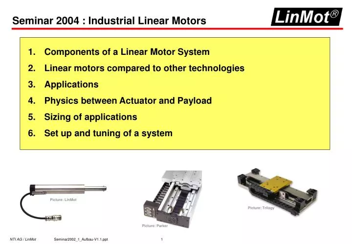
Seminar 2004 : Industrial Linear Motors. Components of a Linear Motor System Linear motors compared to other technologies Applications Physics between Actuator and Payload Sizing of applications Set up and tuning of a system. Picture: LinMot. Picture: Trilogy. Picture: Parker.

E N D
Seminar 2004 : Industrial Linear Motors • Components of a Linear Motor System • Linear motors compared to other technologies • Applications • Physics between Actuator and Payload • Sizing of applications • Set up and tuning of a system Picture: LinMot Picture: Trilogy Picture: Parker
1. Components of a Linear Motor System 1. Components of a Linear Motor System 1.1. Function of a Linear Motor 1.2. Components of Linear Motor Systems 1.2.1. Actuator / Motor 1.2.2. Current source/Amplifier 1.2.3. Closed-loop /open-loop Systems 1.2.4. Force/Velocity/Position controller 1.2.5. Position measurment / Encoders 1.3. Technical data of Linear Motors 1.4. Different designs of Linear motors Bild: LinMot Bild: Trilogy Bild: Parker
Slider Stator Stator Slider 1.1. Function of a Linear Motor (1) Stator Rotating Motor Rotor - cut - ‘flatten’ Flat Linear Motor Picture: SKF ‘roll up into cylinder’ Tubulare linear motor
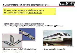
1.1. Function of a Linear Motor (1) • Electromagnetic Linear Motors are based on the same physical laws as rotating motors. • Basically all types of electrical motors can be built as rotating or linear motors. • Because of the outstanding performance of power and control most of the linear motors used for industrial applications are based on the principle of the brushless synchronous motors with permanent magnets. First picture of a linear motor (Mr. Wheatstone 1845)
1.2.1. Actuator / Motor Lorenz Force:= i x B i:= current B:= magn.Induction Magnets: Neodynium N coils Iron flux passage B S B i “right hand role”
A B 1.2.2. Current Source/Controller E.g. : cf = 40 N/A I = 2 A F:= 40N/A / 2 A := 80 N F:= cf * I I=current, cf = force constant of motor (cf or Kt) Commutation and Idealization of the motor Phase current A Force Req Force (+/- 10V) PWM modulated source Internal position measurement B A/B Digital signal processing Commutation: Generation of the phase currents in accordance to the requested force and direction signal based on the actual position betwen slider and stator Idealization: Linearization of the force („dealing with noise, e.t.c. „) Digital Signal processing: Position signal processing and creation of the A/B-Encoder signals
1.2.3. Closed-loop / Open-loop System Closed-loop System • Position is controlled • Position will never get lost • Position will continuously be corrected Requested Position v-controller Force Position controller Istposition d/dt (‘feedback’) Open-loop System • - most of the stepper motor solutions • steps can be lost permanent position error! Requested positon controller
1.2.4. Force-/Velocity-/Position controlling Force controlled The drive system is an idealized force controller (Amplifier/Motor). The real motion controlling will be done by a motion control card. Reference Force Force Actual Position Actual Position (‘feedback’) Velocity controlled The drive system builts a idealized velocity control unit. Disadventageous is that the motion parametesare spread into two systems (linear motor system and position control system). Reference Velocity v-controller Force Actual Position d/dt (‘feedback’) Reference Position Position controlled I/O coupling between machine control and position control system. v-controller Force Position controller Actual Position d/dt (‘feedback’)
Interpolated evaluation of the magnetic field A B 1.2.5. Position measurement / Sensors (1) slider S N S N S N • Internal hall sensors recognize the magnetic field and therefore the relative position between slider magnets and stator coils. • The exact position inside of a magnetic pole can be evaluated with the interpolated- evaluation of the magnetic field. • The absolute position is calculated based on the homing sequence during power on. (E.g. Moving slider against a mechanical stop). • Because of the feedback signals from the position sensors ‘steps’ can not be lost. Hall sensors Neodynium magnets im Läufer erzeugen ein NSNS-Feld Magnetic field more or less ‘sinusoidal’ N S N S N S N S N S N S N S N S N S N S N Example:A(t1):= 3V B(t1):= -2V t1 t1 • AB- evaluation defines direction of movement • Counting of increments (--> position compared to initial position) • Sin/Cos-evaluation leads to position inside of one increment
1.2.5. Position measurement / Sensors (2) Hall sensors Sensor Magnetic tape Internal Sensors External Sensors (Information based on Hall sensors integrated (Information based on sensor head and magnetic tape or optical system) Into the stator) + compact robust solution + highest accuracy + no additional cabeling - assembling (allignment and labor, ..) + no assembly nor adjustments - limited accuracy * With additional motion control board
Air Flange* Forced air Max. Power dissipation [W] P01-23x160 Mounted flange 120 100 100 Flange forced air * Verlustleistung bei Nennkraft gemäss Datenblatt 80 55 Mounted flange with Forced air 60 37 40 28 25.1 17* 11.2 20 Water cooling 0 1.3. Technical data of linear motors Power Class of controller Fpeak Velocity The peak force is always printed for the velocity v:= 0 m/s. The maximum Force is reduced with increased velocity. The value of the peak force can be defined by the manufacturer (be careful !!). For real application the connection between max and continuous force is important and should be calculated with a sizing program. (normally the peak force is about 3-5 time the contiunous force.) The needed continuous force in realapplications must be calculated with a sizing program. The type of cooling is of greatest importance. Select the work range so that the motor is in the range of max force generated, (theflat of the curve).
Sensors Magnets Trailing chain cable bearing Picture: Trilogy coils 1.4. Different designs of Linear Motors (1) Dimensions, cabeling and sensors as well as the bearing systems are in real world applications all critical. Additionaly the engineer has to deal with questions about set up of the system and the needed maintenance during operation. Every linear motor design makes sense (there is no ‚best design‘, only the design best for your applicat.) • Flat design „U“-shape design • High magnetic force between slider and stator • Flat design • no magnetic force betwen slider and stator • moving part without iron Sensors Trailing chain cable Coils Magnets Bearing Picture Parker The linear motor is offered as a kit (magnetic rail, coils, sensors) for integration in a mechanical construction or as assembled linear axes.
1.4. Different designs of Linear Motors (2) Tubular design Microprocessor (Position sensors, serial number, adjusting functions, ...) ‚Stand-alone‘ cable coils Magnets ‚tubular motor with external bearing system‘ Internal Positions- Senss Bearing system (slider bearing based on POM ( DELRIN)) • magnetic force between stator and slider is balanced! Picture: Held AG The linear motos is an integrated systems ( including sensors and bearing systems) for stand-alone applications no additional components needed (end switches etc. ), no assembly and adjustments Depending on the application additional components can be adapted (external sensors for higher accuracy, external bearing systems for high side load or accurate guidance bearings)
1.4. Different designs of Linear Motors (3) Production of tubulare linear motors