Download
1 / 56
570 likes | 586 Views
NOT YET COMMERCIALLY AVAILABLE FUEL CYCLES Near Term (within 20 years). Coal Direct Liquefaction. Liquefaction is divided into two categories: indirect and direct.

E N D
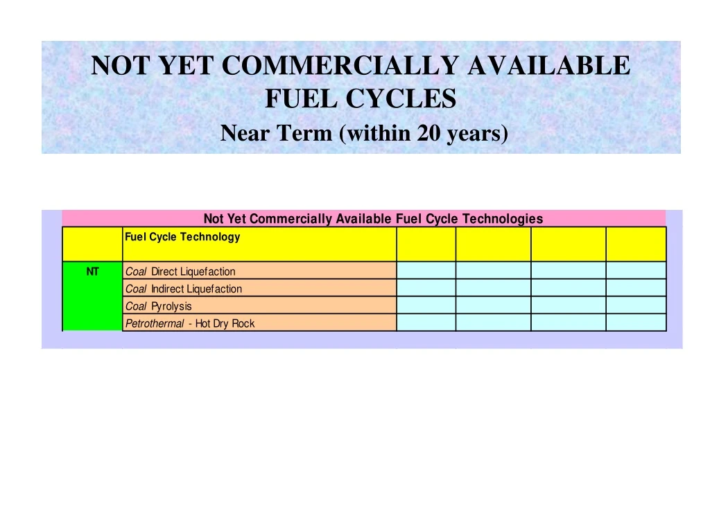
NOT YET COMMERCIALLY AVAILABLE FUEL CYCLESNear Term (within 20 years)
Coal Direct Liquefaction • Liquefaction is divided into two categories: indirect and direct. • Direct liquefaction uses the process of gasification to produce chemicals, such as methanol, for use in manufacturing other products. • Direct liquefaction is also known as hydroliquefaction because the process involves large amounts of hydrogen. • Direct liquefaction is accomplished by crushing coal and mixing it with a solvent to produce a 'slurry'. • Hydrogen is added and the "hydrogenated slurry" is heated and pressurized to produce a synthetic gas and liquid oils such as gasoline, diesel fuel and kerosene.
Coal Indirect Liquefaction • Can produce methanol from coal-derived synthesis gas using the LPMEOH™ process. • LPMEOH™ process has been developed to enhance integrated gasification combined-cycle (IGCC) power generation by producing a clean burning, storable liquid fuel (methanol) from the clean coal-derived gas. • Methanol has a broad range of commercial applications; it can be substituted for conventional fuels in stationary and mobile combustion applications and is an excellent fuel for utility peaking units. • Methanol contains no sulfur and has exceptionally low NOx characteristics when burned.
Coal Indirect Liquefaction - DME • The chemical that replaced fluoro-chloro carbons in spray cans may also serve as a new fuel for power generation, domestic use and transport, according researchers. • DME or dimethyl ether is a clean and safe fuel that is normally produced by dehydration of methanol, but can also be made from natural gas, coal or biomass. In addition to its applications in power generation, domestic fuel use and diesel engines, DME has a potential use in fuel cells. It is environmentally benign and can be handled like LPG. • Diesel fuel has a cetane of 45 while DME has a cetane of 55. DME has no natural lubricating properties and will need a lubricating additive.
Coal Indirect Liquefaction – DME Uses • DME has many uses: • LNG substitute • LPG substitute • Diesel substitute • Ultra clean GT fuel • Synthesized to gasoline • Aerosol • Chemicals
Coalor Biomass Pyrolysis • CHP via biomass gasification connected to gas-fired engines or gas turbines can achieve higher electrical efficiencies between 22-37 % compared to biomass combustion with steam generation and steam turbine (15-18 %). • If produced gas is used in fuel cells for power generation, an even higher overall efficiency between 25-50 %, even in small scale biomass gasification plants and under partial load operation. • Potential reduction in CO2 and NOX may be achieved due to higher electrical efficiency or when used in fuel cells instead of gas-fired engines or GTs. • Pyrolysis of biomass generates three different energy products in different quantities: coke, oils and gases.
Coal or Biomass Pyrolysis • Flash pyrolysis gives high oil yields, but because of the technical efforts needed to process pyrolytic oils, this energy generating system does not seem to be very promising at the present stage of development. • However, pyrolysis as a first stage in a two-stage gasification plant for straw and other agricultural feedstocks deserves consideration. • Power generation in high-temperature MCFC or SOFC with integrated biomass gasification also has the advantage that no separate unit is needed for CO-shift reaction prior to gas injection into the fuel cell, and that in addition to electricity, process heat is provided by the fuel cell at a high temperature level.
Petrothermal - Hot Dry Rock • The above diagram shows a plant called a Hot Dry Rock (HDR) or petrothermal electricity generation plant. Brine (saltwater) is pumped into holes drilled into hot rock, and heated. The hot brine is then used to heat a working fluid called iso-butane which becomes a gas used to drive the turbine. The turbine is connected to the alternator which produces electricity. The ISO Butane gas is kept in a closed system and is re-used. The brine is also re-used by pumping it back to the HDR.
NOT YET COMMERCIALLY AVAILABLE POWER GENERATION TECHNOLOGIESNear Term (within 20 years)
Oil & Gas Advanced GT CyclesIntercooled Steam Recuperated GT (SRGT) • GT has an efficiency of 37% without recuperation, increasing by 25% and increased mass flow through the engine with recuperation. Fuel savings are 10% at full power and 50% at idle, (off-peak running is important in navy ships, where they run for 25-33% full power for most of the time). • Recuperator is a full counterflow PFHE, tension brazed, and is rated at 16 MW (the engine’s ISO rating is 25 MW). It uses a high grade stainless steel. It operates in an environment where corrosion and creep can occur. • Typical duty is cooling 70 kg/s gas from 575oC to 275oC. The temperature difference between the top and bottom of the recuperator is 300oC.
Oil & Gas Advanced GT CyclesChemically Recuperated GT (CRGT) • There are 2 methods to reduce CO2 from power plant flue gas: physical and chemical absorption (with liquefaction of CO2 removed). • Using the advanced mixed cycle (AMC) achieves CO2 emissions of about 0.04 kg/kWh and electrical efficiency of 50% compared to 38.4% for IGCC and 47.8% for CC. • The AMC is a mixed gas-steam cycle consisting of a reheat GT with steam injection in the 1st combustion chamber, a ST for steam expansion a HRB for superheated and resuperheated steam generation (reheater) and atmospheric separator for water recovery from exhaust gas mixture.
Oil & Gas Advanced GT CyclesHumid Air Turbine (HAT) • Converting the heat in a GT exhaust into steam and then converting steam into electric power through a conventional steam cycle involves losses and inefficiencies which reduce the overall cycle efficiency. Adding water up to 25% by weight raises performance. • One feature of a GT is that it already has a turbine creating mechanical power from a flowing gas stream, and this power output can be raised (within limits) by increasing the mass flow of gas. • The flue gas can be cooled by injecting water which evaporates as it cools the gas and increases the mass flow of gas through the GT. Injecting steam from the waste heat boiler into the GT upstream or in the combustion chamber further raises the mass flow. • Such cycles are known as Humid Air Cycles and can raise efficiency by about 3% points compared to a standard IGCC plan and 30% lower NOX emissions.
Oil & Gas Advanced GT Cycles Cascaded Humid Air Turbine (CHAT) • CHAT is essentially a reheat HAT cycle with a turbocharger to allow very high pressures in the saturator (65-70 atm) and higher than the 25% mass fractions of the HAT cycle. • The high-pressure humidified stream is heated in the high-temperature air furnace (HITAF), expanded to drive the turbocharger, reheated in the HITAF, and then heated further in the duct heater before expansion in the turbine. The HAT and CHAT cycles can be in the 55-60% (HHV) range and perhaps higher. • At comparable turbine inlet temperatures, the CHAT cycle yields more power than the HAT cycle. • CHAT could enjoy a 20% advantage in capital cost v.s. CCGT.
GT CHAT Cycle: regeneration or recuperation, compressor intercooling, reheating, water injection
Oil & Gas Advanced GT Cycles Intercooled Reheat Combined Cycle (IRCC) • Intercooled and reheat cycles have a lower efficiency than that of a simple-cycle gas turbine at low-to-moderate pressure ratios. • The main effect of intercooling or reheating is to reduce the size and cost of the basic equipment by increasing the specific power output of the turbine. • However, the lower cost of the basic smaller unit is offset by the added cost of an intercooler or additional combustor and a more complicated turbine design to reheat the gases. • Intercooling with regeneration (recuperation) is more efficient than reheat with regeneration. Regenerators and intercoolers are also more susceptible to leakage – more downtime & costs.
Oil & Gas Advanced GT CyclesIntercooled Aeroderivative (ICAD) • COMPOUND CYCLE – consists of an intercooler, reheater and regenerator (no water or steam). Such a combination results in high thermal efficiencies over a wide range of pressure rations and yields high specific power outputs.
Oil & Gas Advanced GT CyclesEfficiency Improvements in Combined Cycles
Oil & Gas Advanced GT CyclesCurrent & Projected Efficiencies
Coal Pressurized Fluidized Bed Combustion (PFBC) 1st generation pressurized fluidized bed combustor uses a "bubbling-bed" technology. A relatively stationary fluidized bed is established in the boiler using low air velocities to fluidize the material, and a heat exchanger (boiler tube bundle) immersed in the bed to generate steam. Cyclone separators are used to remove particulate matter from the flue gas prior to entering a gas turbine, which is designed to accept a moderate amount of particulate matter (i.e., "ruggedized").
Coal Pressurized Fluidized Bed Combustion (2) • Fluidized-bed combustion evolved from efforts to find a combustion process able to control pollutant emissions without external emission controls (such as scrubbers). • The technology burns fuel at temperatures of 1,400 to 1,700 degrees F, well below the threshold where nitrogen oxides form (at approximately 2,500 degrees F, the nitrogen and oxygen atoms in the combustion air combine to form nitrogen oxide pollutants). • Mixing action of the fluidized bed brings the flue gases into contact with a sulfur-absorbing chemical, such as limestone or dolomite. More than 95 percent of the sulfur pollutants in coal can be captured inside the boiler by the sorbent.
Coal Pressurized Fluidized Bed Combustion (3) • Pressurized fluidized-bed combustion builds on earlier work in atmospheric fluidized-bed combustion technology. Atmospheric fluidized bed combustion is crossing over the commercial threshold, with most boiler manufacturers currently offering fluidized bed boilers as a standard package. • Popularity of FBC is due largely to the technology's fuel flexibility - almost any combustible material, from coal to municipal waste, can be burned - and the capability of meeting sulfur dioxide and nitrogen oxide emission standards without the need for expensive add-on controls. • An estimated 1000 megawatts of capacity installed worldwide now use pressurized fluidized bed to generate sufficient flue gas energy to drive a gas turbine and operate it in a combined-cycle.
Coal Pressurized Fluidized Bed Combustion (4) • Pressurization effectively reduces the size of the fluidized bed boiler and raises efficiency from 47% to 50% compared to a huge conventional pulverized coal-fired boiler.
Coal Pressurized Circulating Fluidized Bed Combustion (PCFBC) • A 2nd generation pressurized fluidized bed combustor, currently under development, uses "circulating fluidized-bed" technology and a number of efficiency enhancement measures. • Circulating fluidized-bed technology has the potential to improve operational characteristics by using higher air flows to entrain and move the bed material, and recirculating nearly all the bed material with adjacent high-volume, hot cyclone separators. • The relatively clean flue gas goes on to the heat exchanger. This approach theoretically simplifies feed design, extends the contact between sorbent and flue gas, reduces likelihood of heat exchanger tube erosion, and improves SO2 capture and combustion efficiency.
Coal Integrated Gasification Combined Cycle (IGCC) • Major improvement of 2nd generation PFBC is the integration of a coal gasifier to produce a pressurized fuel gas that goes to a topping combustor and adds to the combustor's flue gas energy entering the GT, the more efficient unit of CCGT. The waste heat is recovered in the bottoming heat recovery steam generator. • An advanced IGCC power plant, incorporating high temperature gas cleaning and GT with high firing temperatures, could achieve a power generation efficiency of 50% (LHV) within the next 10 to 15 years. • This increase of efficiency will consequently result in a lower CO2 emission i.e 660 g/kWh. Such an IGCC power plant will also have 50% lower emissions of NOx and SO2.
A Texaco based IGCC power plant:Mass & Energy Balances (Net Efficiency = 42%)
The first European commercial scale, IGCC power plant at Buggenum, The Netherlands Where the GT is fired on a gas fuel derived from the gasification of liquid or solid carbonaceous materials, the cycle is known as an Integrated Gasification Combined Cycle (IGCC). An IGCC can convert "difficult" liquid and solid fuels to electricity at high efficiencies and with low emissions.
IGCC for fossil fuel, such as vacuum residue, heavy oil, petroleum coke, coal and Orimulsion
Coal Integrated Gasification Humid Air Turbine (IGHAT) • In conventional gas turbines, more than a third of the power generated in the expander is absorbed to compress the working fluid. This loss of exergy is increased by the requirement for an excess air flow to allow cooling of the turbine components. • Humid air turbines (HAT) allow for lowering this inconvenient disadvantage in two ways: • - First, they use intercoolers on a multistage compressor, therefore reducing the power requirement of compression and producing low temperature heat. • - Secondly, moisture is added to the compressed air (20-40%). Low grade heat is used to produce hot water. This heat is recovered from the compressor intercooler, aftercooler and turbine exhaust.
Coal Integrated Gasification Humid Air Turbine (2) • When HAT is integrated with a coal gasifier (IGHAT), there is a large amount of heat available from the gasifier and other processes (including air separation plant for oxygen blown gasifiers). • The hot water is brought into contact with the compressed air in a counter current saturator. Humid air leaving the saturator may have a moisture content of 20% (natural gas HAT) and 40% (IGHAT). • This is a key stage of the HAT cycle, since the saturator is a multistage column and this heat exchange approaches reversibility. The humid air is further heated against the hot turbine exhaust in the recuperator.
Coal Integrated Gasification Humid Air Turbine (3) • The variable boiling point working fluid of steam and air avoids the large temperature divergence between the water and turbine exhaust in a gas turbine combined cycle. • Thus, the moisture addition increases the work output from the turbine, while the intercooling reduces the compressor work requirement. • This combines to increase the net power output. The IGHAT cycle can achieve efficiencies higher than those of conventional combined cycles, and is especially adapted for base-load electricity production. • An additional feature of this cycle is that, given the high moisture content of the exhaust gas, it is particularly well-suited for district heating. Biomass can also be used in the IGHAT.
Coal Brayton Cycle Direct Coal-Fired Combustion:DCF, DCFCC (Combined Cycle) • The research on direct coal firing (DCF) in gas turbines has been carried out for over forty years. The initial difficulties were related to the severe effects of coal ash on turbine blade path components (corrosion, erosion and deposition). • Latter-day effort on DCF has concentrated on developing high pressure (12-16 bar) slagging coal combustors which allow removal of ash as a liquid prior to entering the turbine. • The hot gas clean up must take place above the ash melting temperature (1400-1600ºC) and high pressure (at least 18 bar). This high temperature provides additional gains in exergy with respect to other advanced coal cycles, such PFBC or IGCC. The molten ashes accumulate on the edge of the slagging chamber by a centrifugal effect.
Coal Brayton Cycle Direct Coal-Fired Combustion:DCF, DCFCC (2) • DCFCC (combined cycle) is not yet a proven technology, its state of development being still in the laboratory phase. • Apart from the slagging combustion system and the liquid ash and contaminants removal, however, all other components of DCFCC (gas turbine, steam cycle, etc.) are commercially available technologies. • A study carried out by Westinghouse/Gilbert-Commonwealth Inc. in 1990 investigated the economics of DCF gas turbines fitted with slagging combustion technology. • The study concluded that the cost of electricity from this plant type could be 11-18% cheaper than a comparable 220 MWe pulverised coal boiler fitted with FGD.
Coal Brayton Cycle Direct Coal-Fired Diesel • Fuels such as orimulsion or refinery bottoms can yield substantial cost savings for large diesel engines. • The technology challenge is how to use these abrasive fuels when injecting coal water slurry directly into a diesel engine cylinder. • The technology is still under study.
Geothermal Liquid Dominated Binary Plant Kalina Cycle • This plant is estimated to be up to 40-50% more efficient than existing standard binary Rankine cycle geothermal power plants. • The Kalina cycle uses an ammonia-water mixture(85-15 % by weight) as the working fluid and takes advantage of regenerative heating. • Binary plants are usually sized in 10 MW modules. • The ammonia-water mixture has a low boiling point, therefore, the excess heat coming from the turbine's exhaust can be used to vaporize a substantial portion of the working fluid. • The Kalina cycle would therefore transfer substantially less heat to the environment. An efficiency improvement would also mean that more electricity is being produced per pound of brine.
Geothermal Liquid Dominated Binary Plant Kalina Cycle (2) Schematic diagram of a binary cycle plant
Geothermal Liquid Dominated Binary Plant Kalina Cycle (3) • The hot brine from the geothermal well is used firstly to both superheat and reheat the working fluid and then to evaporate and preheat it before being reinjected into the ground. • The working fluid, in superheated condition, is expanded through the H.P.turbine stages and then reheated before entering the L.P.turbine stage. After the second expansion, the saturated vapour moves through a recuperative boiler before being condensed in a water cooled condenser. • The two recuperative heat exchangers (HE-4 and HE-2) provide approximately 38% of the total heat transferred to the working fluid, thus improving net brine effectiveness (higher kWh/kg brine). Standard steam turbines are used because ammonia and water are similar (M.W. of 17 and 18).
Geothermal Liquid Dominated Binary Plant Kalina Cycle (4) Schematic diagram of a Kalina cycle plant (with regenerative heating)
Municipal Solid Waste RDF Co-Firing (e.g. 20% coal) • Municipal solid waste (MSW) is one of three major waste-to-energy technologies (the others are anaerobic digestion and biomass). • MSW can be directly combusted in waste-to-energy facilities: (1) as a fuel with minimal processing, known as mass burn; (2) it can undergo moderate to extensive processing before being directly combusted as refuse-derived fuel (RDF); (3) or it can be gasified using pyrolysis or thermal gasification techniques. • Each of these technologies presents the opportunity for both electricity production as well as an alternative to landfilling or composting the MSW.
Municipal Solid Waste RDF Co-Firing (2) • In contrast with many other energy technologies that require fuel to be purchased, MSW facilities are paid by the fuel suppliers to take the fuel (known as a "tipping fee"). • The tipping fee is comparable to the fee charged to dispose of garbage at a landfill. • Refuse-derived fuel (RDF) typically consists of pelletized or fluff MSW that is the by-product of a resource recovery operation. Processing removes ferrous materials, glass, grit, and other materials that are not combustible. The remaining material is then sold as RDF. Both the RDF processing facility and the RDF combustion facility are located near each other, if not on the same site.
Municipal Solid Waste RDF Co-Firing (3) • The RDF can then be used in one of several configurations: (1) dedicated RDF boilers designed with traveling grate spreader- stokers; (2) co-firing of RDF with coal or oil in a multi-fuel boiler; and (3) dedicated RDF fluidized-bed boiler. • In 1998, a 10.5 MW commercial RDF facility in the City of Commerce, California, was operated by the Los Angeles County Sanitation District. • RDF is now a successful technology in a number of locations where dedicated boilers were selected rather than attempting to co-fire with other fuels. Currently there are 26 RDF plants working in the US processing some 27,000 tpd of RDF (Kiser & Zannes, 2000).
Municipal Solid Waste RDF Co-Firing (4) Batch-Type Incinerator Design Traveling Gate Incinerator Design
Municipal Solid Waste Gasification (Pyrolysis/Thermal) • Pyrolysis is the thermal decomposition of organic material at elevated temperatures in the absence of gases such as air or oxygen. The process, which requires heat, produces a mixture of combustible gases (primarily methane, complex hydrocarbons, hydrogen and carbon monoxide), liquids and solid residues. • Thermal gasification of MSW is different from pyrolysis in that the thermal decomposition takes place in the presence of a limited amount of oxygen or air. The producer gas which is generated can then be used in either boilers or cleaned up and used in combustion turbine/generators. • The primary area of research is the scrubbing of the producer gas of tars and particulates at high temperatures in order to protect combustion equipment and still maintain efficiency.