Download
1 / 10
120 likes | 290 Views
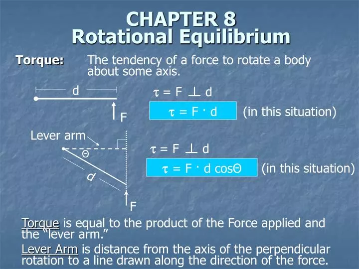
d. F. = F d. = F d. Lever arm. Θ. = F · d. (in this situation). d. = F · d cos Θ. (in this situation). F. Torque: The tendency of a force to rotate a body about some axis. CHAPTER 8 Rotational Equilibrium.

E N D
d F = F d = F d Lever arm Θ = F · d (in this situation) d = F · d cosΘ (in this situation) F Torque: The tendency of a force to rotate a body about some axis. CHAPTER 8Rotational Equilibrium Torque is equal to the product of the Force applied and the “lever arm.” Lever Arm is distance from the axis of the perpendicular rotation to a line drawn along the direction of the force.
Center of Gravity Center of Gravity of an Object 1. For a symmetrical object, the Center of Gravity is usually intuitively obvious. It is at the intersection of the x and y lines of symmetry. 2. For non-symmetrical objects, the Center of Gravity is easily calculated (as in the next example) or it is provided to you. 3. Calculus is used to find the Center of Gravity for very non-symmetrical objects. You are not expected to know how to use calculus to find centers of gravity.
xcg = m1x1 + m2x2 + m3x 3+m4x4 m1 + m2 + m3 + m4 Example 0 1 2 3 4 xcg = m(.5) + 2m(1.5) + m(2.5) + m(3.5) 5m xcg = 1.9 Center of Gravity of an Object Torque calculations often involve Fg. Calculations of Torque are simplified if all the mass in the object can be thought of as existing at one point in the object. Center of Gravity xcg = weighted average lever arm about an end pivot point Notice that this approach to the problem used symmetry to find the center of mass of each individual block.
FN=200N F=100N B 20kg 1.0m F=100N A Fg=200N Frictionless Surface Third Condition for equilibrium: Net = 0 Torque and Equilibrium Fx,Net = 100N–100N = 0 N Fy,Net = 200N–200N = 0 N Will the box begin to accelerate in any direction? Yes, because the third condition for equilibrium is not met. Net = CW - CCW • Strategy for determining Net • Pick a convenient rotational point (pivot point) • A or B in this case • A convenient pivot point has a zero lever arm and zero torque Calculate and Sum the Torques (A = pivot point) A = 0 N (100N · 0 m = 0 N·m) B = 100N · 1.0m = 100 N·m (CCW) Net = -100 N·m (CCW)
33kg FP 40kg A B 5.5m x 5.5 - x Using Torque to Solve “Statics” Problems Statics Problems: System is in static equilibrium. Fx,Net = 0 N Fy,Net = 0 N Net = 0 N·m Three equations make it possible to solve for up to three unknowns. Example Problem (Seesaw) A 40kg child and a 33kg child are to be balanced (static equilibrium) on a 5.5m seesaw. Where must the pivot point be placed relative to the smaller child? What is the upward force at the fulcrum? Problem Solving Strategy: Sketch the Problem
FP = 720N 33kg FP 40kg A B 5.5m x 5.5 - x Choose a convenient pivot point (the fulcrum in this case). Set up the three equations and solve for the unknowns FNet,x = 0 N No Data FNet,y = 0 N FP = FA + FB = (33kg)(9.8m/s2)+(40kg)(9.8m/s2) Net = 0 N·m (33kg)(9.8m/s2)(x) = (40kg)(9.8m/s2)(5.5 – x) x = 3.0 m
15,000kg 1500kg FPress FC1 5.0m FBeam FC2 10.0m 20.0m Example Problem (Forces on Table Supports) A uniform 20.0m, 1500kg beam supports a 15,000kg printing press 5.0m from the right support column. Calculate the force on each support column. Sketch the Problem Notice how Centers of Gravity are used to simplify problem. Choose a Convenient Pivot Point Either left or right column could be used. Choose left.
1500kg 15,000kg FPress FC1 5.0m FBeam FC2 10.0m 20.0m FC2 = 118,000 N FC1 = 44,000 N Set up three equations and solve for unknowns. FNet,x = 0 N No Data FNet,y = 0 N FC1 + FC2 = FBeam + FPress FC1 + FC2 = (1500kg)(g) + (15,000kg)(g) FC1 + FC2 = 162,000 N Net = 0 N·m FC1 (0M) + FBeam (10.0m) + FPress (15.0m) = FC2 (20.0m) (14,700N)(10.0m) + (147,000N)(15.0m) = FC2 (20.0m)
FT FT,y FH FH,y 30° FH,x FT,x m=280kg Fg,Beam Fg,Block 2.20m Example Problem (Beam and Wire) A uniform beam 2.20m long with mass of 25.0kg is mounted by a hinge on a wall and rests horizontally when supported by a wire connecting the outside end of the beam to the wall. The wire makes an angle of 30° to the horizontal. A 280.kg mass is suspended from the far end of the beam. Determine the components of force that the hinge exerts on the beam and the component of the tension force in the wire. Sketch the Problem Show the Forces and their components
FT,y = 2870 N FH,y = 120N FT,x = 4970 N FH,x = 4970 N FT FT,y FH FH,y 30° FH,x FT,x m=280kg Fg,Beam Fg,Block 2.20m Choose a Convenient Pivot Point (Hinge) Setup the Three Equations and solve for three unknowns FNet,x = 0 N FH,x = FT,x FNet,y = 0 N FH,y + FT,y = Fg,Beam + Fg,Block Net = 0 N·m (Fg,Beam)(1.10m) + (Fg,Block)(2.20m) = (FT,y)(2.20m) Plug and Solve (Hint: FT,y=FT,xtan30 is a 4th equation to use)