Download
1 / 26
300 likes | 504 Views
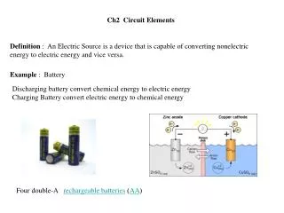
Diode As Circuit Elements. Section 3.1-3.3. Key Concepts. Diode models Exponential model Derivation of n Ideal model Constant-voltage model. Choosing a Diode Model. Use the ideal model to develop a quick, rough understanding of a circuit.

E N D
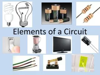
Diode As Circuit Elements Section 3.1-3.3
Key Concepts • Diode models • Exponential model • Derivation of n • Ideal model • Constant-voltage model
Choosing a Diode Model Use the ideal model to develop a quick, rough understanding of a circuit. If the ideal model is not adequate, uses the constant voltage model, which is sufficient for most cases. Occasionally, we will use the exponential model
c02f31 IS=Reverse Saturation=leakage current
Ideal Model of a Diode (exponential model) (ideal model) An ideal diode will turn on even for the slightest forward bias voltage. (VD≥0) An ideal diode will turn off even for the slightest reverse bias voltage. (VD<0)
c03f03 Behavior of Ideal Diode Ideal diode: Vanode>Vcathode: Diode is on Vanode<Vcathode: Diode is off An ideal current experieincing Vanode=Vcathode, carries no current
c03f05 I/V Characteristics A short--can’t get a V to develop across a diode. An Open—can’t get a current to flow. A diode Vanode>Vcathode: Diode is on Vanode<Vcathode: Diode is off An ideal current experieincing Vanode=Vcathode, carries no current In practice, consider a slightly positive or negative voltage to determine the response of a diode.
c03f08 Example 1: An OR Gate Realized By Diodes
Analysis of an OR Gate Logic 1=3 V Logic 0=0V • Observations: • If D1 is on, VA=VOUT and VOUT=“1” • If D2 is on, VB=VOUT and VOUT=“1”. • VOUT is 0 if and only if D1 and D2 are “0” • This is an OR gate.
Example of an OR Gate VA=3 V VB=0 V VOUT=2.424 V≈3V
In Class Exercise VA VB
In Class Exercise If VA=“0”, node 1 is “0”. If VB=“0”, node 1 is “0”. If both VA and VB are “1” or 3V, no current can flow through R1, node 1 is 3 V. So we have an AND gate. Assume node 2 is 3V. VA VB
Simulation Example VA=3V VB=0V VOUT=0.575 V
Simulation Example VA=3V VB=3V VOUT=3 V
In-Class Exercise What is logic implemented by A, B and LED?
Solution 0 V 0 V
Decimal to Binary Converter Big idea: If you deprive an LED with current,it will turn off. If you provide an LED with current, it will turn on.
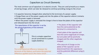
c02f33 Constant Voltage Model If VD is less than VD, On, the diode behaves like an open circuit. The diode will behave like an open circuit for VD=VD,on
Analysis of an OR Gate Logic 1=3 V Logic 0=0V • VA=3V, VB=0V • Observations: • D1 is ON. • VD1=0.7V • So VOUT=2.3 V • D2 is OFF
Example of an OR Gate VA=3 V VB=0 V VOUT=2.424 V≈3V (ideal diode model) ≈2.3 V (constant voltage model)
Limitations of Diode Logic Circuit Vout=1.23 V
Level Shift Vout of 606 mV Vout can depend on input voltage combination!