Download
1 / 68
680 likes | 685 Views
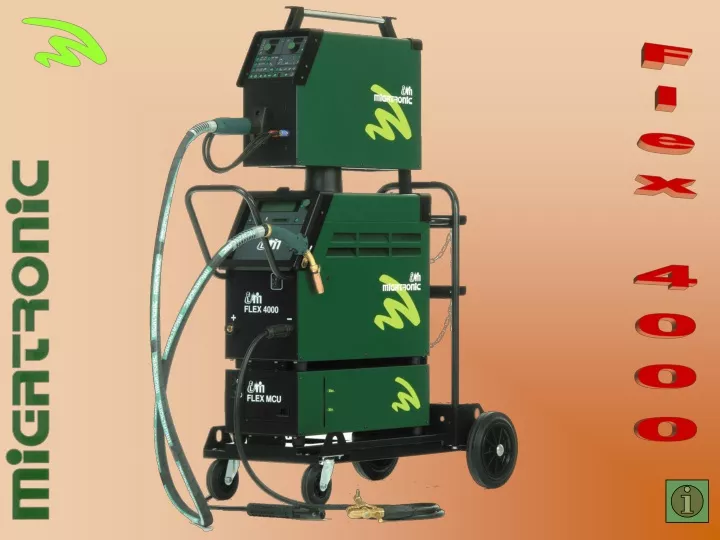
Forside. Flex 4000. Flex overboks. Flex kortlæser. Mains error indicator. The LED lights in case of over voltage or under voltage, under or over 15% variation, and will be lit for 5 seconds after correction of the error.

E N D
Forside Flex 4000
Mains error indicator The LED lights in case of over voltage or under voltage, under or over 15% variation, and will be lit for 5 seconds after correction of the error. The LED for mains error will flash, if the power source is defective, to indicate that service must be sent for.
Overheating of torch Indicates interruption of welding due to overheating of the torch. After sufficient cooling of the torch welding can be resumed. The LED lights for 5 seconds after the torch has cooled and flashes if the torch is defective.
Error in wire feed motor Indicates interruption of welding due to overloading of wire feed motor. The LED is lit for 5 seconds after correction of the error. The LED flashes if the wire feed motor is defective. The LED flashes simultaneously with the LED for temperature error, if the error is caused by overconsumption of current in the wire feed motor. The LED flashes to indicate that service must be sent for.
Gas pressure error Indicates interruption of welding due to too low or too high pressure on the gas supply. The LED lights for 5 seconds after correction of the error. In synergic programs the gas flow regulator will automatically regulate the correct gas flow as a parameter. The LED flashes in case of errors in the gas flow regulator to indicate that service must be sent for.
Overheating of power source Shows interruption of welding due to overheating of the power source. The LED lights for 5 seconds after correction of the error. The LED flashes simultaneously with the LED for wire feeding error if the error is caused by overconsumption of current in the wire feed motor. The LED flashes to indicate that service must be sent for.
Adjustment of current and wire Used for setting the welding current or wire feed speed. The function of the dial depends on choice of program, i.e. a synergic or a manual welding program. The dial is infinite and moves in clicks. A click to the right increases the digit on the display, and a click to the left reduces the digit.
Setting of parameter Used for setting all parameters except welding current and wire feed speed. The function of the dial depends on the chosen adjustable parameter. Trim and welding current (V) are set by pressing the button next to the dial. The dial is infinite and moves in clicks. A click to the right increases the digit on the display, and a click to the left reduces the digit.
Choice of welding proces Alternatives: MIG/MAG or MMA welding Flex 4000 is a multi process welding machine.
Key pad method Key pad method can be chosen in MIG/MAG. By pressing the key pad, either two-stroke or four-stroke control of the welding process is chosen.
With or without pulse This function can be used in MIG/MAG when a synergic program has been chosen in the program unit. The function changes between welding with or without pulse, but with the same wire and gas set-up. Shifts between synergic pulse and no pulse during welding is possible in connection with the use of sequential shifts.
Two-stroke or four-stroke Two-stroke Welding is started by pressing down the torch trigger. Welding will continue until the trigger is released, after which slope down will begin. The machine can be reactivated during slope-down and gas post-flow. Four-stroke Welding is started by pressing down the torch trigger. Welding will continue after the trigger is released. The next press on the trigger activates slope down and interrupts the welding process.
Setting of control By pressing the button for setting of control you will get the following alternatives: internal control, remote control or Migatronic Dialog torch control. If you choose a MIG/MAG synergic welding program, only the requested welding current is set. In MIG/MAG manual mode, wire feed speed and voltage are set. In MMA mode only the requested welding current is set.
Machine control The dial at the right side of the control panel is for setting the current or wire feed speed. The dial at the left side is for setting the voltage (v) manually; the same dial is used as a trim function of voltage if a synergic welding program is chosen.
Remote control Flex 4000 can be fitted with remote control for adjustment of wire and voltage. If remote control is chosen, the internal dials for adjustment of current and wire feed speed are deactivated.
Dialog torch Torch control can be chosen and utilized in the MIG/MAG process if the machine is fitted with Migatronic Dialog torch. When torch control is chosen, current speed and wire feed speed can be set both from the dial on the welding torch and from the dial internally on the weldng machine. In a synergic program the torch control can be used to either turn on or turn down the welding current by up to 100 A from the current set on the machine, provided that parameters are within the program range. Also in a manual program it will be possible to turn down the wire feed speed by up to 10 m/min. In torch control trim or voltage are set with the dial like in internal control.
Program display • In the digital display the program is presented with name and the following details: • if the program is placed on smart card • if the welding program is MIG or MMA process • if the program is synergic • if pulse is chosen • if there are any errors • Additional details on the display: • wire material • diameter of the wire • chemical composition and mixing proportion of the gas • polarity of the MIG torch • any other parameters
Smart card reader A MIGATRONIC smart card containing up to 50 standard or tailor-made welding programs can be inserted in the machine. The digital system ensures full reproducibility of welding programs which can easily be transferred between machines. New smart cards with programs adjusted to all future applications can be ordered via Migatronic’s program data bank. The light beside the smart card indicates when the machine is using the card.
Dial The dial will display the programs available on the card or factory-made programs when the dial is turned. The program in the display switches by a click to the right or to the left. Names of programs are presented on the clear display as a rolling list.
Key pad for choice of program A program is chosen by pressing the key pad for choice of program. The welding machine will only function if a program from the program data bank is chosen. If there is no smart card in the machine when starting, a factory-made program is chosen. The machine will automatically start in the program chosen last time the machine was in use.
Units, left • A switch to one of these indicators when a parameter is chosen will ensure harmony between parameter and units. • Possible units are: • - Display for current - A (ampere) • - Display for wire feed speed - m/minute
Units, right • A switch to one of these indicators when a parameter is chosen will ensure harmony between parameter and units. • Possible units are: • - Display for trim / voltage / chosen parameter • - V - volt • - l/min - litre per minute • - S - seconds • - % - percentage • - mm - millimetre
Display, right If the welder does not choose an adjustable parameter, either voltage or volt trim is displayed in MIG/MAG, while in MMA voltage is always displayed. If a parameter is chosen, the value of the chosen parameter is displayed. When the arc is extinguished, the mean value of the voltage is shown for five seconds in the display. If sequence is used, the mean value for the latest welded sequence is displayed.
Display, right - continued Adjusted trim and voltage have the same adjustment area, meaning that since trim can be set between -9,9 V and 9,9 V, the voltage for a synergic voltage value of e.g. 24,0 V can be set between 14,1 V and 33,9 V. It is possible to choose between adjustment of trim or voltage by pressing down the V-dial for at least two seconds, when adjusted voltage or trim is shown in the display. In MIG manual mode without simple synergy, voltage is shown in the display when the welding machine is not used. Voltage can be set between 10 V and 50 V. During welding with MIG synergic pulse at frequences faster than 2 hz, a mean value of the measured voltage is continuously shown. At frequences under 2 hz measured base and pulse voltage in the respective periods are shown. In MMA the measured voltage or output is shown whether the welding machine is in use or not. In MMA voltage cannot be adjusted. When the arc is extinquished, the weld mean value of the voltage is shown in the display for 5 seconds. In sequential welding only the weld mean value of the latest welded sequenc is displayed. If the V-dial is pressed during the display of voltage or trim, and the machine is not in use, the latest weld mean value for the voltage is displayed for five seconds. It is not possible to change the value of trim or voltage as long as the weld mean value is displayed. It is possible, however, to press the V-dial once more or to press one of the dials for the other parameters while weld mean value is displayed. This will result in immediate interruption of the display of the weld mean value.
Display, left In MIG either the current or wire feed speed is shown in the display, while in MMA the current is always displayed. If a MIG synergy program without pulse is chosen, a mean value of the measured current is continuously shown in the display during welding. When the machine is not in use, the set current is displayed. If a MIG synergy program with pulse mode is chosen, the set mean welding current is shown when the machine is not in use. During welding a mean value of the measured current is continuously displayed. If a manual MIG program is chosen, actual current is shown in the display during welding, while the set wire feed speed is displayed when the machine is not in use. In MMA actual current is shown in the display during welding. When the machine is not in use, the set current is displayed.
Display, left - continued It applies especially to wire-inching that the measured values for wire feeding are displayed as long as the function is maintained by pressing down the wire-inching key pad. When the arc is extinguished, the weld mean value of the current is shown in the display for five seconds. The weld mean value is the average from establishment of the arc until extinction of the arc, except if sequence is used, in which case the weld mean value is the average from start until end of the sequence. In case of sequential welding, only the weld mean value for the latest welding sequence is shown. The weld mean value for the latest welding is also shown for five seconds, if the V-dial is pressed down and if voltage or trim is already shown in this display and if the machine is not in use. It is possible to press once more on the V-dial or to press one of the dials for the other parameters while the weld mean value is displayed. This will result in immediate interruption of the display of the weld mean value. In MMA the current can be set between a minimum current of 15 A and the maximum current of the machine. In synergic MIG pulse/no pulse mode the current can be set between the synergic minimum and the synergic maximum current in the program, but not higher than the maximum current of the machine. Wire feed speed in manual MIG can be set between 1 m/minute and the maximum wire feed speed. If simple synergy is chosen, there are restrictions on wire feed speed. The current is set in whole ampere, i.e. without decimal points. Wire feed speed is set in m/minute (with one decimal).
Arc power Arc power is an arc enhancing function used to stabilize the arc in MMA welding. This is done by briefly increasing the welding current during the unintended short circuits. The additional current is cut out when there is no longer a short circuit. Arc power can be set between 0 and 150 % of the pre-set welding current.
Arc-adjust Arc-adjust (electronic choke). An auxiliary function for spatter-free welding, pleasant welding sound and fine ignition properties. Dip transfer: In dip transfer Arc-adjust makes it possible to adjust the reaction time for short circuits. Arc-adjust value varies between 1 and 100. Spray transfer: In spray transfer there will be no short circuits, for which reason Arc-adjust is not important. Pulse welding: Arc-adjust cannot be chosen in a pulse program, since Arc-adjust is always in synergy in pulse welding.
Thickness of material Thickness of material can be chosen in a synergic program. This function is a help to adjust the synergic current on the basis of the thickness of the material. When thickness of material is chosen, a synergic current will be adjusted automatically, corresponding to the specific thickness of material in case of welding from above. The synergic current can be adjusted subsequently. As a principal rule the thickness of material is stated as standard roller thicknesses for the actual material.
Extra line With this extra line key pad it is possible in certain programs to get further details about the program. The next press on the extra line key pad will switch back to the name of the program.
Machine lock The user has the option of ”keying" a valid code by turning the dial. The code is chosen between 000 and 999. A turn to the right gives value 0 - 999, and a turn to the left gives values -999 - 0. The code is accepted by the user by two short presses on the key pad. The code prevents unintended use of the machine and theft.
MigaNet MigaNet is the internal electronic Can-Bus circuit which continuously circulates digital signals in the welding machine. MigaNet is a self detecting system, meaning that any possible set-up of the machine is adjusted and registered automatically.
Cooling of torch In MIG/MAG welding there are two alternatives: water cooling or air cooling of torch and intermediary cables. Cooling method is chosen, when the welding machine is not in use. It is to be recommended to choose water cooling of the torch in severe operation, and in general, in case of high current in the spray transfer area and in case of pulse welding.
Tack welding If tack-welding is chosen, the key pad method is always two-stroke. With this function it is possible to switch between the actual welding program and tack-welding. This function is often used for tack-welding of workpieces prior to the actual welding job.
Welding voltage The welding voltage LED lights for safety reasons when the MIG torch or the MMA electrode is under voltage.
Indication of arc The LEDs are placed in a graph indicating whether the MIG process is in dip transfer, globular transfer or spray transfer. If a synergic program is chosen, the actual process level will be indicated both before and during welding. If a manual MIG program without synergy is chosen, there will be no indication.
Gas flow Gas flow means the protection gas flowing through the gas nozzle during welding. The gas flow can be set from minimum 3 litres per minute up to maximum gas flow. In synergic programs the gas quantity will be a program parameter. When gas flow is chosen, the actual gas flow is displayed during welding.
Gas pre-flow Gas pre-flow is the period of time for which gas flows after the torch trigger is pressed and before wire feeding begins. In synergic programs gas pre-flow will be a program parameter. Gas pre-flow is adjustable and is set between 0.0 and 10 seconds.
Gas post-flow Gas post-flow ensures protection of the weld pool after welding, protects the wire end and cools the torch. In synergic programs gas post-flow will be a program parameter. The gas post-flow time is the period from the extinction of the arc to the interruption of the gas supply. Gas post-flow is adjustable and can be set between 0 and 20 seconds.
Creep start Creep start improves ignition properties considerably, especially during welding with high wire feed speed, since this function prevents the wire from ”stopping”. This key pad is used for setting the starting wire feed speed. The speed can be set between 0.5 and the actually chosen wire feed speed, or corresponding to the chosen synergy current.
Welding process This field visualizes and collects parameters essential to the welding process in MIG/MAG and MMA. By pressing the key pads the LEDs will light in the individual welding phases. When a LED switches on, this parameter can be read and adjusted, if necessary.
Sequence Use the dial under the left display for setting the number of sequences Use this key pad to switch between sequences Display shows the chosen sequence Sequences can be used both in MIG/MAG and MMA and can be chosen when internal control is chosen. Sequence makes it possible to switch between different settings of parameters during arc welding.
Hot start Hot start can be used in: MMA welding MIG/MAG welding
Hot start time Setting of hot start time When this diode is on, the hot start time may be set using the potentiometer below the right display. The display will show the set hot start time in secs.
Hot start MMA Hot start MMA is an auxiliary function for establishment of the arc when welding starts. Especially when welding with basic electrodes, hot start is very applicable. This is done by automatically increasing the welding current for some milliseconds when the electrode touches the workpiece. The increased start amp is maintained after which it decreases to the set value for welding current. The hot start value can be set between 0 and 100% of the set current.
Hot start MIG/MAG Hot start is an auxiliary function for establishing the right temperature in the weld pool when welding is started. MIG/MAG hot start is applicable in two-stroke as well as four-stroke. In two-stroke the hot start function cannot be controlled with the torch trigger and is therefore fixed as regards time. In four-stroke hot start is controlled with the torch trigger.
Burn-back The burn-back function ensures that the wire does not stick to the weld pool. Burn-back is set as a value from 1 to 30 (with no unit). Burn-back is the period of time from when the wire feeding stops till the current is switched off. This new Migatronic machine ”cuts” the wire on a Peak in synergic pulse welding programs.
Sequence slope time This parameter can be chosen if sequence is used. Sequence slope time makes it possible to gradually change parameters between sequences. This will prevent development of craters in connection with sequence shifts. Slope up/slope down takes place in the period of time chosen in the parameter (0-10 secs). The chosen parameter will diplay whether the next sequence is higher or lower than the previous sequence. If no sequence slope time is set, the time will be 0 secs.