Download
1 / 1
10 likes | 291 Views
CONCLUSION. PURPOSE. INTRODUCTION. METHODS. RESULTS. DISCUSSION. Title Insert Here Title Insert Here Title Insert Here Title Insert Here Title Insert Here Title Insert Here .

E N D
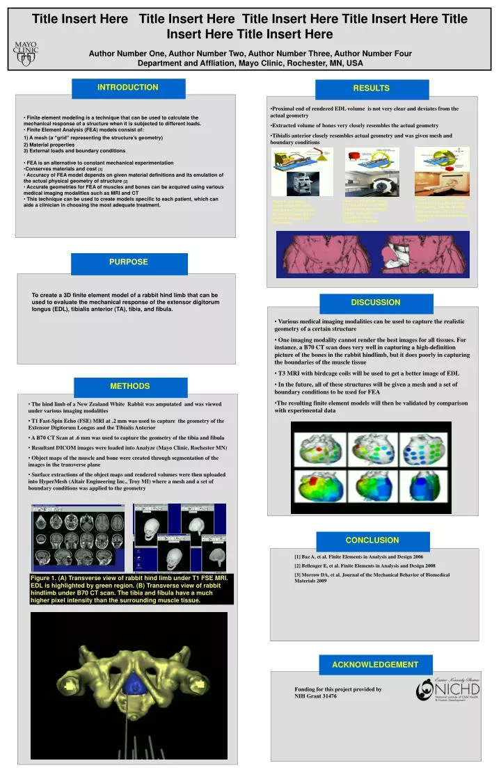
CONCLUSION PURPOSE INTRODUCTION METHODS RESULTS DISCUSSION Title Insert Here Title Insert Here Title Insert Here Title Insert Here Title Insert Here Title Insert Here Author Number One, Author Number Two, Author Number Three, Author Number FourDepartment and Affliation, Mayo Clinic, Rochester, MN, USA • Proximal end of rendered EDL volume is not very clear and deviates from the actual geometry • Extracted volume of bones very closely resembles the actual geometry • Tibialis anterior closely resembles actual geometry and was given mesh and boundary conditions • Finite element modeling is a technique that can be used to calculate the mechanical response of a structure when it is subjected to different loads. • Finite Element Analysis (FEA) models consist of: • 1) A mesh (a “grid” representing the structure’s geometry) • 2) Material properties • 3) External loads and boundary conditions • FEA is an alternative to constant mechanical experimentation • Conserves materials and cost [2] • Accuracy of FEA model depends on given material definitions and its emulation of • the actual physical geometry of structure [2] • Accurate geometries for FEA of muscles and bones can be acquired using various medical imaging modalities such as MRI and CT • This technique can be used to create models specific to each patient, which can aide a clinician in choosing the most adequate treatment. Insert figure here Figure 4. Rendered volume of TA loaded into HyperMesh (Altair Engineering, Troy MI). A mesh (grid) and a set of boundary conditions (triangles) have been applied. Figure 3. Left image shows CT scan of the bone. Right image shows the rendered volume loaded into HyperMesh (Altair Engineering, Troy MI). Figure 2. Top image shows actual EDL from New Zealand White rabbit [3]. Bottom image shows rendered volume from MR images. • To create a 3D finite element model of a rabbit hind limb that can be used to evaluate the mechanical response of the extensor digitorum longus (EDL), tibialis anterior (TA), tibia, and fibula. • Various medical imaging modalities can be used to capture the realistic geometry of a certain structure • One imaging modality cannot render the best images for all tissues. For instance, a B70 CT scan does very well in capturing a high-definition picture of the bones in the rabbit hindlimb, but it does poorly in capturing the boundaries of the muscle tissue • T3 MRI with birdcage coils will be used to get a better image of EDL • In the future, all of these structures will be given a mesh and a set of boundary conditions to be used for FEA • The resulting finite element models will then be validated by comparison with experimental data • The hind limb of a New Zealand White Rabbit was amputated and was viewed under various imaging modalities • T1 Fast-Spin Echo (FSE) MRI at .2 mm was used to capture the geometry of the Extensor Digitorum Longus and the Tibialis Anterior • A B70 CT Scan at .6 mm was used to capture the geometry of the tibia and fibula • Resultant DICOM images were loaded into Analyze (Mayo Clinic, Rochester MN) • Object maps of the muscle and bone were created through segmentation of the images in the transverse plane • Surface extractions of the object maps and rendered volumes were then uploaded into HyperMesh (Altair Engineering Inc., Troy MI) where a mesh and a set of boundary conditions was applied to the geometry [1] Baz A, et al. Finite Elements in Analysis and Design 2006 [2] Bellenger E, et al. Finite Elements in Analysis and Design 2008 [3] Morrow DA, et al. Journal of the Mechanical Behavior of Biomedical Materials 2009 Figure 1. (A) Transverse view of rabbit hind limb under T1 FSE MRI. EDL is highlighted by green region. (B) Transverse view of rabbit hindlimb under B70 CT scan. The tibia and fibula have a much higher pixel intensity than the surrounding muscle tissue. ACKNOWLEDGEMENT Funding for this project provided by NIH Grant 31476


![[Insert Title Here]](https://cdn3.slideserve.com/6543966/insert-title-here-dt.jpg)
![[Insert Title Here]](https://cdn3.slideserve.com/6833485/insert-title-here-dt.jpg)
![[ Insert Title Here ]](https://cdn4.slideserve.com/8936996/insert-title-here-dt.jpg)