Download
1 / 48
500 likes | 858 Views
AE Senior Thesis 2008. Trump Taj Mahal Hotel Atlantic City, New Jersey. Analysis and Design of a Steel Braced Frame Core An Investigation of the Design of High Rise Steel Structures. Stephen Reichwein Structural Emphasis. Project Information Existing Structural System

E N D
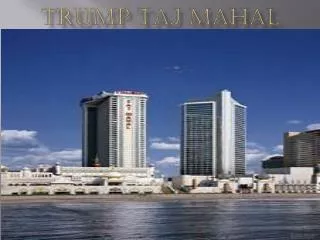
AE Senior Thesis 2008 Trump Taj Mahal HotelAtlantic City, New Jersey Analysis and Design of a Steel Braced Frame Core An Investigation of the Design of High Rise Steel Structures Stephen Reichwein Structural Emphasis
Project Information • Existing Structural System • Problem Statement and Solution • Structural Redesign • Architectural Studies • Construction Studies • Conclusions Presentation Outline
General Information • 40 Story Hotel Tower • Expansion to Existing Hotel • Project Cost = $200 Million • Project Size = 730,000 G.S.F • Owner – Trump Hotels and Casino Resorts • Project Delivery Method – Design Build • Groundbreaking: July 2006 • Completion: August 2008 Project Information
Project Location Project Information Existing Hotel Atlantic Ocean Boardwalk Showboat
Building Architecture • Diamond Footprint • Services in Central Core • Reflective Glass Curtainwall (Shaft) • Stainless Steel Capital • Precast Concrete (Base) 40’ Project Information 60’ 140’ 460’
Project Information • Existing Structural System • Problem Statement and Solution • Structural Redesign • Architectural Studies • Construction Studies • Conclusions Presentation Outline
Gravity System • Filigree Flat Plate (Non-core) • Reinforced Flat Plate (Core) • Concrete Columns (100% Gravity) Existing Structural System Filigree Flat Slab, Typ. Non-core Concrete Column (Gravity) Shear Wall Core Concrete Flat Plate, Typ. Core In-slab Beam, Typ.
Lateral Force Resisting System • Reinforced Concrete Shear Wall Core Existing Structural System SW 2 SW 4 LINK BEAM SW 1 SW 3
Project Information • Existing Structural System • Problem Statement and Solution • Structural Redesign • Architectural Studies • Construction Studies • Conclusions Presentation Outline
Key design consideration: opening the hotel as soon as possible • Erection of concrete system slow and labor intensive • Swallower mat foundation will provide cost and schedule savings • Extremely heavy concrete core requires a 9’-0” thick mat foundation Problem Statement Why was a concrete structure the system of choice?
Reduce structure dead weight using an all steel system • Premium 1: 10” floor to floor height increase • Premium 2: Architectural Impacts • Eliminate costly concrete construction with faster steel erection • Utilize a “core only” lateral force resisting system • Determine why a concrete framing system was chosen over a steel framing system? Design Goals
Lateral System Redesign • Steel Braced Frame Core • Gravity System Redesign • Steel Non-Composite Frame with Precast Concrete Planks Solution Overview
Project Information • Existing Structural System • Problem Statement and Solution • Structural Redesign • Architectural Studies • Construction Studies • Conclusions Presentation Outline
Non-Composite Steel Frame with Precast Planks • Analysis and Design • RAM Steel – LRFD • Typical Dead Load = 98 psf • Typical Live Load = 40 psf • System Takeoff • Girders and Beams: 1000 tons • Gravity Columns: 900 tons • 10” Precast Planks with 2” Topping: 683,000 S.F. • Nitterhouse Structural Redesign
Non-Composite Steel Frame with Precast Planks Typical Bay Framing Structural Redesign
Non-Composite Steel Frame with Precast Planks Typical Bay Framing Structural Redesign
Steel Braced Frame Core Redesigned Core Structural Redesign BF 8 SW 2 BF 2 BF 4 SW 4 Wind tunnel loads provided by DFA BF 7 BF 6 BF 1 SW 1 SW 3 BF 3 BF 5
Steel Braced Frame Core • Behavior • Cantilevered vertical truss • Columns resist moment with axial deformations • Braces resist shear • Primary Drift Components • “Chord Drift” from axial shortening of columns • “Shear Racking” of braces • Strength Design • Slenderness (KL/r) • H1-1a and H1-1b Structural Redesign
Steel Braced Frame Core • Bracing Configurations Structural Redesign BF 1 (E/W): Eccentric Braces 8’-0” Link BF 1 BF 2 BF 3 BF 4 BF 5 BF 6 BF 7 BF 8
Steel Braced Frame Core • Classical Design Methods – Preliminary Analysis and Design • Moment Area Method • Classical Virtual Work Structural Redesign W14x808 (As = 237 in2) << 424 in2 Built-up Sections Required
Steel Braced Frame Core Braced Frame Schedule Structural Redesign
Steel Braced Frame Core • Strength Check • H1-1a and H1-1b • P-delta effects Structural Redesign BF 1 BF 2 BF 3 BF 4 BF 5 BF 6 BF 7 BF 8
Steel Braced Frame Core • Drift Results and Comparison – Wind Tunnel Loads (75%) Structural Redesign
Steel Braced Frame Core • Braced Frame Column Base Plate • A36 PL 65” x 55” x 10-1/2” with (32) 2-3/4” A449 Grade 120 Anchor Bolts • Punching Shear • Pu = 15,910 kips • Mat Thickness Required = 110” ≈ 108” • 9’-0” Thick Mat Foundation Still Required!!!! Structural Redesign
Steel Braced Frame Core • Structural Dynamics – Fundamental Periods • Translation X – East/West • Translation Y – North/South • Torsional - Rotation about Z Structural Redesign
Steel Braced Frame Core • Parametric RMS Acceleration Study Structural Redesign Concrete shear wall core is within target range; however, the steel braced frame core is not!!!!
Steel Braced Frame Core • Solution to RMS Acceleration Issue • Already sufficiently large braced frame members require supplemental mass and damping • Building motion can be alleviated by additional mass and damping Structural Redesign Tuned mass dampers will add approximately $2 to $3 Million to overall project cost
Project Information • Existing Structural System • Problem Statement and Solution • Structural Redesign • Architectural Studies • Construction Studies • Conclusions Presentation Outline
Redesigned Service Core Architectural Studies
Interior Architectural Impacts Architectural Studies
Exterior Architectural Impacts Architectural Studies
Project Information • Existing Structural System • Problem Statement and Solution • Structural Redesign • Architectural Studies • Construction Studies • Conclusions Presentation Outline
Scheduling Comparison Construction Management Studies Steel structure will top out a month earlier than concrete Concrete/Filigree Structural System Steel Structural System
Cost Comparison Construction Management Studies
Project Information • Existing Structural System • Problem Statement and Solution • Structural Redesign • Architectural Studies • Construction Studies • Conclusions Presentation Outline
Long lead time for steel and precast planks offers little schedule advantage (approximately 1 month less than concrete) • Braced frame core performs adequately against strength and drift • Lighter steel frame still requires 9’-0” thick mat foundation • Building accelerations may be perceived by occupants because braced frame core is too flexible • Steel structure will cost approximately $5.5 million more than concrete structure if mass damper is found to be required Conclusions
Because it is stiffer, the concrete shear wall core limits the dynamic movement of the building better than the steel braced frame core • Filigree flat plate system erects much faster than a typical concrete floor system, giving the steel little schedule advantage • With supplemental damping taken into consideration, the concrete system will cost less than steel structure Recommendation
I would like to thank those individuals who have either indirectly or directly helped in making this project possible, taking time out of their busy schedules to answer my questions…. Trump Entertainment Resorts Joseph S. Polisano The Harman Group, Inc. Malcolm Bland Jason Squitierre Bovis Lend Lease Bill Lankford John AdamsKPFF Jeff Albert Friedmutter Group John Koga AE Faculty Advisor Dr. Andres Lepage AE Faculty Professor M. Kevin Parfitt Professor Robert Holland Structural and CM Mentors Charlie Carter Benjamin M. Kovach AE Students Sam Jannotti Jason Sambolt Friends and Family Parents Brothers and Sisters Penn State AE Class of 2008 Acknowledgements
Steel Braced Frame Core • Connection Design and Detailing Structural Redesign STIFFENER, AS REQ’D 10” Floor to Floor Height Increase Required!!!! NOTE: PRECAST PLANK NOT SHOWN FOR CLARITY
25% Wind Force Reduction From AISC Design Guide 3: Serviceability Design Considerations for Steel Buildings
Peak Acceleration ….Can only truly be determined utilizing wind tunnel studies
Steel Braced Frame Core Braced Frame Schedule Structural Redesign
Steel Cost Breakdown Steel Cost Breakdown