Download

1 / 38
580 likes | 1.36k Views
Compression Members. COLUMN STABILITY. A. Flexural Buckling Elastic Buckling Inelastic Buckling Yielding B. Local Buckling – Section E7 pp 16.1-39 and B4 pp 16.1-14 C. Lateral Torsional Buckling. AISC Requirements. CHAPTER E pp 16.1-32. Nominal Compressive Strength. AISC Eqtn E3-1.

E N D
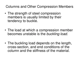
COLUMN STABILITY • A.Flexural Buckling • Elastic Buckling • Inelastic Buckling • Yielding • B. Local Buckling – Section E7 pp 16.1-39 • and B4 pp 16.1-14 • C. Lateral Torsional Buckling
AISC Requirements CHAPTER E pp 16.1-32 Nominal Compressive Strength AISC Eqtn E3-1
AISC Requirements LRFD
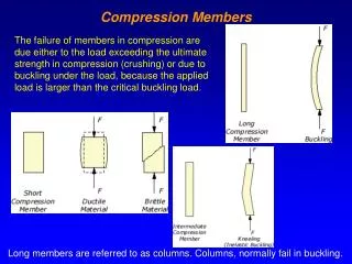
Local Stability - Section B4 pp 16.1-14 Local Stability: If elements of cross section are thin LOCAL buckling occurs The strength corresponding to any buckling mode cannot be developed
Local Stability - Section B4 pp 16.1-14 Local Stability: If elements of cross section are thin LOCAL buckling occurs The strength corresponding to any buckling mode cannot be developed
Local Stability - Section B4 pp 16.1-14 • Stiffened Elements of Cross-Section • Unstiffened Elements of Cross-Section
Local Stability - Section B4 pp 16.1-14 • Compact • Section Develops its full plastic stress before buckling (failure is due to yielding only) • Noncompact • Yield stress is reached in some but not all of its compression elements before buckling takes place (failure is due to partial buckling partial yielding) • Slender • Yield stress is never reached in any of the compression elements (failure is due to local buckling only)
Local Stability - Section B4 pp 16.1-14 If local buckling occurs cross section is not fully effective Avoid whenever possible Measure of susceptibility to local buckling Width-Thickness ratio of each cross sectional element: l If cross section has slender elements - l> lr Reduce Axial Strength (E7 pp 16.1-39)
Slenderness Parameter - Limiting Values AISC B5 Table B4.1 pp 16.1-16
Slenderness Parameter - Limiting Values AISC B5 Table B4.1 pp 16.1-17
Slenderness Parameter - Limiting Values AISC B5 Table B4.1 pp 16.1-18
Slender Cross Sectional Element:Strength Reduction E7 pp 16.1-39 Reduction Factor Q: Q: B4.1 – B4.2 pp 16.1-40 to 16.1-43
Slender Cross Sectional Element:Strength Reduction E7 pp 16.1-39 Reduction Factor Q: Q=QsQa Qs, Qa: B4.1 – B4.2 pp 16.1-40 to 16.1-43
COLUMN STABILITY • A.Flexural Buckling • Elastic Buckling • Inelastic Buckling • Yielding • B. Local Buckling – Section E7 pp 16.1-39 • and B4 pp 16.1-14 • C. Torsional, Lateral/Torsional Buckling
Torsional & Flexural Torsional Buckling When an axially loaded member becomes unstable overall (no local buckling) it buckles one of the three ways • Flexural Buckling • Torsional Buckling • Flexural-Torsional • Buckling
Torsional Buckling Twisting about longitudinal axis of member Only with doubly symmetrical cross sections with slender cross-sectional elements Cruciform shape particularly vulnerable Standard Hot-Rolled Shapes are NOT susceptible Built-Up Members should be investigated
Flexural Torsional Buckling Combination of Flexural and Torsional Buckling Only with unsymmetrical cross sections 1 Axis of Symmetry: channels, structural tees, double-angle, equal length single angles No Axis of Symmetry: unequal length single angles
Torsional Buckling Eq. E4-4 Cw = Warping Constant (in6) Kz = Effective Length Factor for Torsional Buckling (based on end restraints against twisting) G = Shear Modulus (11,200 ksi for structural steel) J = Torsional Constant
Lateral Torsional Buckling 1-Axis of Symmetry AISC Eq. E4-5 Coordinates of shear center w.r.t centroid of section
Lateral Torsional Buckling No Axis of Symmetry Fe is the lowest root of the Cubic equation AISC Eq. E4-6
In Summary - Definition of Fe Elastic Buckling Stress corresponding to the controlling mode of failure (flexural, torsional or flexural torsional) Fe: Theory of Elastic Stability (Timoshenko & Gere 1961) Flexural Buckling Torsional Buckling 2-axis of symmetry Flexural Torsional Buckling 1 axis of symmetry Flexural Torsional Buckling No axis of symmetry AISC Eqtn E4-4 AISC Eqtn E4-5 AISC Eqtn E4-6
EXAMPLE Compute the compressive strength of a WT12x81 of A992 steel. Assume (KxL) = 25.5 ft, (KyL) = 20 ft, and (Kz L)= 20 ft FLEXURAL Buckling – X axis WT 12X81 OK Ag=23.9 in2 Inelastic Buckling rx=3.50 in ry=3.05 in
Shear Center EXAMPLE FLEXURAL TORSIONAL Buckling – Y axis (axis of symmetry) WT 12X81 OK Ag=23.9 in2 rx=3.50 in ry=3.05 in y=2.70 in tf=1.22 in Ix=293 in4 Iy=221 in4 J=9.22 in4 Cw=43.8 in6
EXAMPLE FLEXURAL TORSIONAL Buckling – Y axis (axis of symmetry) WT 12X81 Ag=23.9 in2 rx=3.50 in ry=3.05 in y=2.70 in tf=1.22 in Ix=293 in4 Iy=221 in4 J=9.22 in4 Cw=43.8 in6
EXAMPLE FLEXURAL TORSIONAL Buckling – Y axis (axis of symmetry) WT 12X81 Ag=23.9 in2 rx=3.50 in ry=3.05 in y=2.70 in tf=1.22 in Ix=293 in4 Iy=221 in4 J=9.22 in4 Cw=43.8 in6
EXAMPLE FLEXURAL TORSIONAL Buckling – Y axis (axis of symmetry) WT 12X81 Elastic or Inelastic LTB? Ag=23.9 in2 rx=3.50 in ry=3.05 in y=2.70 in tf=1.22 in Ix=293 in4 Iy=221 in4 J=9.22 in4 Cw=43.8 in6
EXAMPLE FLEXURAL TORSIONAL Buckling – Y axis (axis of symmetry) WT 12X81 Ag=23.9 in2 rx=3.50 in ry=3.05 in y=2.70 in tf=1.22 in Ix=293 in4 Iy=221 in4 Compare to FLEXURAL Buckling – X axis J=9.22 in4 Cw=43.8 in6
Column Design Tables Assumption : Strength Governed by Flexural Buckling Check Local Buckling Column Design Tables Design strength of selected shapes for effective length KL Table 4-1 to 4-2, (pp 4-10 to 4-316) Critical Stress for Slenderness KL/r table 4.22 pp (4-318 to 4-322)
EXAMPLE Compute the available compressive strength of a W14x74 A992 steel compression member. Assume pinned ends and L=20 ft. Use (a) Table 4-22 and (b) column load tables (a) LRFD - Table 4-22 – pp 4-318 Fy=50 ksi Table has integer values of (KL/r) Round up or interpolate
EXAMPLE Compute the available compressive strength of a W14x74 A992 steel compression member. Assume pinned ends and L=20 ft. Use (a) Table 4-22 and (b) column load tables (b) LRFD Column Load Tables Tabular values based on minimum radius of gyration Fy=50 ksi
Example II A W12x58, 24 feet long in pinned at both ends and braced in the weak direction at the third points. A992 steel is used. Determine available compressive strength Enter table 4.22 with KL/r=54.55 (LRFD)
Example II A W12x58, 24 feet long in pinned at both ends and braced in the weak direction at the third points. A992 steel is used. Determine available compressive strength Enter table 4.22 with KL/r=54.55 (ASD)
Example II A W12x58, 24 feet long in pinned at both ends and braced in the weak direction at the third points. A992 steel is used. Determine available compressive strength CAN I USE Column Load Tables? Not Directly because they are based on min r (y axis buckling) If x-axis buckling enter table with
Example II A W12x58, 24 feet long in pinned at both ends and braced in the weak direction at the third points. A992 steel is used. Determine available compressive strength X-axis buckling enter table with