Download
1 / 16
230 likes | 695 Views
Analytical Modeling of Surface and Subsurface Initiated Fretting Wear. Arnab Ghosh Ph.D. Research Assistant. Outline. Motivation & Background Surface Initiated Fretting Wear Simulation of fretting Stress based wear model (Damage Mechanics) Effect of friction, hardness and Young’s modulus

E N D
Analytical Modeling of Surface and Subsurface Initiated Fretting Wear Arnab Ghosh Ph.D. Research Assistant
Outline • Motivation & Background • Surface Initiated Fretting Wear • Simulation of fretting • Stress based wear model (Damage Mechanics) • Effect of friction, hardness and Young’s modulus • Subsurface Initiated Fretting Wear • Use of Linear Elastic Fracture Mechanics (LEFM) • Crack propagation criteria • Crack paths and life calculations • Effect of friction and normal load on life
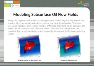
Motivation and Background Subsurface crack initiation - Ductile fracture initiated by formation of microcracks at interface between precipitates - Subsequent removal of material in fretting wear happens due to delamination (Waterhouse, 1977) Cross section of specimen showing surface cracks. (Nishioka & Hirakawa, 1969) Cracks caused by alteration of the friction forces acting on surfaces of actual contact (Hirano & Goto, 1967) Intergranular fracture of ball bearing steel due to hydrogen embrittlement (Scott, 1968) Surface Crack Initiation Alternating tensile and compressive stresses induce fatigue crack formation around the regions of surface contact. The direction of propagation of these cracks is clearly associated with the direction of the contact stresses. Crack formation underneath the wear track of annealed copper (Suh, 1973) Fracture surface showing crack extension by alternating shear (wavy slip region) – (Pelloux, 1970)
Simulation of Fretting in FEA Partial Slip A 2 dimensional Hertzian line contact with plain strain condition is simulated in FEA to study the stress states at different stages of fretting. Gross Slip Von Misses stress and fretting loops at the interface It can be observed that high contact stresses are observed in the slip regions and therefore, surface damage (wear) can be related to these stresses. Each Voronoi cell is divided into Constant Strain Triangle elements Voronoi Tessellation FEA mesh Steel microstructure 2D Voronoi tessellations incorporate randomness in the microstructure and geometrically simulate the grain morphology observed in reality.
Stress based Wear Model ENERGY BASED WEAR EQUATION DAMAGE EVOLUTION Fs: Shear Force Fp=PloughingForce Fp= 0 (for surfaces with similar hardness and roughness) Generalized damage equation: (E Rabinowicz) Damage Law derived for Wear equation: (Amonton) (Fouvry et al) INTERGRANULAR CRACK PROPAGATION Grain removal (Crack surrounds a grain) D Dc Crack at grain boundary Crack Propagtes along the grain boundary in CCW direction Simulating wear by removing grains at the contact interface
Wear Propagation Evolution of contact pressure as wear progresses Archard’s Law: From the Damage Mechanics model: The coefficient kGS thus obtained is compared to Archard’s wear coefficients found in literature Comparison of wear scars with experiments
Effect of Coefficient of Friction H=4GPa, E=200 GPa H=2.5GPa, E=200 GPa H=1GPa, E=200 GPa A critical value of µ was observed between 0.25 and 0.5 for the mentioned input parameters. Increasing µ beyond 0.5 doesn’t change wear rate considerably. Wear rate vs Coefficient of Friction V@10,000 : Wear Volume after 10000 cycles calculated using the equation
Effect of Hardness µ=0.5, E=200 GPa µ=0.75, E=200 GPa µ=1.0, E=200 GPa Wear rate vsHardness
Effect of Young’s Modulus µ=0.5, H=4 GPa µ=0.5, H=2.5 GPa µ=0.5, H=1 GPa It has been shown that for low cycle fatigue wear of dry and smooth contacts , the wear coefficients are of the order of 10-3 to 10-2 (Challen & Oxley, 1986) Wear rate vsYoung’s Modulus
Subsurface Crack Propagation • Linear Elastic Fracture Mechanics is used to propagate subsurface cracks • An initial crack of length 5 is created at depth of 10 from the contact surface • Alternating shear stress is observed at both the crack tips • A mode II fracture mechanism is assumed LEFT CRACK TIP RIGHT CRACK TIP Shear stress reversal at the 2 crack tips Detailed view of the Left crack tip
Use of Linear Elastic Fracture Mechanics (Mode II) Under compressive load (Hertzian Pressure), Mode I growth is suppressed and Mode II growth is more predominant. Linear Elastic Fracture Mechanics (LEFM) can be used to find the direction of crack growth Check for LEFM assumption The plastic zone size: CYCLIC PLASTIC ZONE The crack extension, therefore needs to be a value higher than is the fracture toughness and for plane strain is given by: is the yield stress of the material 52100 steel properties are used: = 1220 , = 18 CRACK MONOTONIC PLASTIC ZONE
Crack Propagation Direction The radial shear stress at the crack tip is given by: The alternating shear stress is given by Stress Intensity Factors (SIFs) ~ Modified Crack Closure Technique For plane strain, Possible crack paths Valid for , but Crack Tip Opening Displacement is restricted under compressive load and MCCT can be used for higher . In the current model, The crack propagates in the direction of maximum alternating shear stress
Crack Tip Mesh Refinement • The mesh around the crack tip is refined within a radius of • A refined mesh around the crack tip is required to • Obtain a more accurate singular stress field • Propagate crack within the refined region. • An automatic adaptive mesh refinement is used which moves with the crack tip and maintains the same level of refinement as the crack grows. Crack Growth showing adaptive meshing around crack tip Rp= 2.88 CYCLIC PLASTIC ZONE REFINED MESH ZONE (r=5 CRACK Crack Tip mesh refinement and the von Mises stress field = 3 Regions around crack tip and crack extension
Crack Paths and Life =0.1 10 • Initial Crack Dimensions: • Length: 5m • Depth from Contact Surface: 10 • As coefficient of friction increases the span of the crack when it reaches the surface decreases. This is due to decrease in slip with increase in . • As Hertzian Pressure increases, the span of the crack as it reaches the surface decreases. As the applied load increases, the slip decreases 5 =0.3 =0.6 Growth of Initial Crack for different values of Coefficient of Friciton PH=0.5 GPa • Life is defined as the number of cycles till the crack reaches surface, after which material will be removed. • In the current model, life is calculated using the Paris’ Law: • For Martensitic steel, • C=1.36 x 10⁻¹⁰ m/cycle MPa√m • m=2.25 PH=1 GPa PH=2 GPa Growth of Initial Crack for different values of Hertzian Pressure
Effect of Different variables on Life PH Approaching partial slip Life decreases PH=0.5 GPa • Life decreases with increase in applied load • Effect of at higher loads is negligible • Life decreases with increase in . • Shear Force, Q=P • Life Decreases significantly with increase in Shear Force. PH=1 GPa PH=2 GPa Life vs applied pressure at different values of coefficient of friction Life vs Shear Force (Q) Log-log plot of Life vs Shear Force Log(N) = -1.39 Log (Q) +11.3
Summary • Surface initiated fretting wear can be modeled by damage mechanics using only standard material properties • Wear rate decreases with increase in Hardness and Young’s modulus • Increasing coefficient of friction beyond 0.5 doesn’t impact wear rate • The wear coefficients obtained from the model are comparable to Archard’s wear coefficient • Sub surface initiated fretting wear can be modeled by Linear Elastic Fracture Mechanics • Alternating shear stress at crack tips drives crack propagation. Crack direction is calculated using a Mode II criteria • Crack path is studied for different combinations of variables • Paris’s Law is used to calculate the Life • Life decreases with increase in applied load and coefficient of friction Future Work • Incorporate plasticity effects and model hardness in the stress based damage mechanics model • Study the effect of grain size and surface roughness • Extend the LEFM model to study cracks at different depths from the contact surface • Model stress risers (inclusions, void) in the domain and study its effect on crack path • Combine Damage Mechanics and LEFM: Subsurface crack initiation using damage mechanics and propagation using LEFM