Download
1 / 58
580 likes | 584 Views
This guide provides an introduction to software design, review of architectural design, and detailed design process and activities. It covers topics such as requirements analysis, design verification and validation, implementation, testing, and operation and maintenance.

E N D
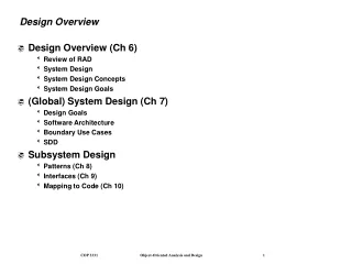
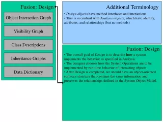
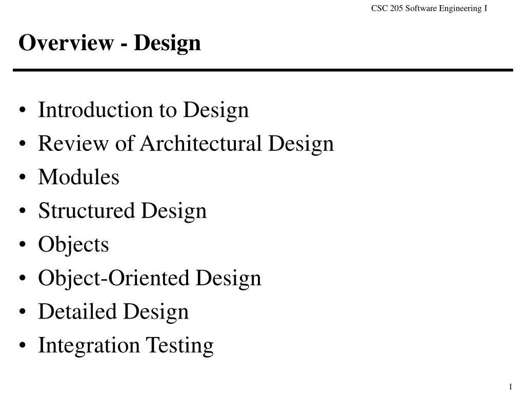
Overview - Design • Introduction to Design • Review of Architectural Design • Modules • Structured Design • Objects • Object-Oriented Design • Detailed Design • Integration Testing
Goals and Objectives • Develop a coherent representation of a software system that will satisfy the requirements • Identify inadequacies in the requirements • Develop review plan that demonstrates coverage of the requirements • yields confidence in design • Develop test plan that covers design • yields confidence in both design and implementation
Introduction to Design R e q u i r e m e n t s C h a n g e V a l i d a t i o n Requirements Analysis + Specification V a l i d a t i o n How ? Design V e r i f i c a t i o n Implementation andIntegration T e s t i n g Operation andMaintenance R e v a l i d a t i o n
Relationship to other lifecycle phases • Requirements • Specifies the “what” not the “how” • Provides conceptual boundaries • keeps design focused • Implementation • Design stops and coding begins when design specifications are sufficient for coding assignments • each assignment, theoretically, can be given to a programmer unaware of the overall system architecture
Basic Design Process • The design process develops several models of the software system at different levels of abstraction • Starting point is an informal “boxes and arrows” design • Add information to make it more consistent and complete • Provide feedback to earlier designs for improvement Informal design outline Informal design More formal design Finished design
Top-Down Design • Recursively partition a problem into sub-problems until tractable (solvable) problems are identified System level subsystem level module level
Design Activities • Architectural design • Subsystem identification • services and constraints are specified • Module design • modular decomposition is performed; relationships specified • Detailed design • Interface design • module interfaces are negotiated, designed and documented • Data structure and algorithm design • module details (data structures and algorithms) to provide system services are specified
Design Products • Refined requirements specification • Description of systems to be constructed • software architecture (diagram) • modular decomposition (hierarchy) • abstract module interface specifications • detailed module designs • Documentation of decisions and rationale • Data dictionary of all defined objects • Validation review plan • Integration test plan
Uniform Complete Rigorous Confirmable, verifiable, testable Supportable by tools Desensitized to change Accommodates independent coding Depth-first design: only partial satisfaction of requirements Failure to consider potential changes Too detailed: overly constrains implementation Ambiguous: misinterpreted during implementation Undocumented: designers become essential Inconsistent: system cannot be integrated Desirable Characteristics/ Common Problems
Architectural Design • Architectural Design • decomposition of large systems that provide some related set of services + establishing a framework for control and communication • Architectural styles establish guidelines • a relatively new area of research • No generally accepted architectural design process • some important sub-processes • System structuring: structuring of the system into a number of subsystems, where a subsystem is an independent software unit • Control modeling: establishing a general model of control relationships between the parts of the system • Modular decomposition: decomposing each identified subsystem into modules
Software Architecture • Components • The elements out of which the system is built • Examples: filters, databases, objects, ADTs • Connectors • The interaction or communication mechanisms • The glue that combines the components • Examples: procedure calls, pipes, event broadcast, messages, secure protocols • Constraints • Limitations on the composition of components and connectors
Architectural Style • Example architectural styles • Batch sequential • Pipe and filter • Main program and subroutines • Blackboard • Interpreter • Client-server • Communicating processes • Event systems • Object-oriented • Layered Systems Families of systems defined by patterns of composition
Architectural Design:System Structuring • Model of the system structure and decomposition • how subsystems share data • how they are distributed • how they interface with each other • Three standard models • Repository model:how subsystems exchange and share information • E.g., all shared data is held in a central database or each sub-system maintains its own database • Distribution model: how data and processing is distributed across a range of processors • E.g., Client-server or peer-to-peer processes • Abstract machine model:the interfacing of subsystems as abstract machines each of which provides a set of services to others • E.g., each subsystem defines an abstract machine
Architectural Design:Control Modeling • Control of subsystems so that services are delivered to the right place at the right time • Two general approaches • Centralized control • One subsystem has overall responsibility for control and starts/stops other subsystems • call-return model (sequential) • manager model (concurrent) • Event-based control • each subsystem responds to externally generated events (from other subsystems or the environment) • broadcast model • interrupt-driven model
Architectural Design:Modular decomposition • After decomposition of the system into subsystems, subsystems must be decomposed into modules • No rigid distinction between system and modular decomposition • Two important approaches for decomposing subsystems into modules: • Data-flow (structured design) • system is decomposed into functional modules which accept input data and transform it to output data • process-based decomposition • achieves mostly procedural abstractions • Object-oriented (object-oriented analysis and design) • system is decomposed into a set of communicating objects • object-based decomposition • achieves both procedural + data abstractions
Architectural Design:Hierarchy • Hierarchies support modular decomposition • Uses relation:auses b only if the correct functioning of a depends on the existence of a correct implementation of b • modular decomposition can be specified by uses, where • Level 0 is the set of all programs that use no other program • Level i ( i > 0) is the set of all programs that use at least one program on level i -1 and no program at level ≥ i. • Note: the uses relation does not always provide a hierarchy • Is-composed-of relation: a is-composed-of b if b is a component of a and encapsulated within a • modular decomposition can be specified by is-composed-of, where • non-terminals are virtual code • terminals are the only units represented by code • Then, the uses relation is specified over the set of terminals only • Note: the is-composed-of relation is acyclic
Modules • Definition: a software entity encapsulating the representation of an abstraction and providing an abstract interface to it • Module interaction • Module hides implementation details so that the rest of the system is insulated and protected from the details AND vice versa • Modules communicate only through well-defined interfaces • Negotiating module interfaces • design interface to component to be insensitive to change • determine likely usage patterns and purposes • disseminate minimal information as useful generalities • abstract Interfaces: one specification, many possible implementations • suppress unnecessary detail of a design decision
Architecture, Subsystems and Modules • Architecture consists of interacting subsystems • determined by application domain • Subsystems • a component whose operation does not depend on the services provided by other subsystems • communicates with other subsystems via defined interfaces • is decomposed further into modules by design methods • Modules • a component that provides one or more services to other modules • not normally considered an independent subsystem
Modular Decomposition:Abstraction • Abstraction is a tool that supports focus on important, inherent properties and suppression of unnecessary detail • permits separation of conceptual aspects of a system from the implementation details • allows postponement of design decisions • Three basic abstraction mechanism • procedural abstraction • specification describes input/output • implementation describes algorithm • data abstraction • specification describes attributes, values, properties, operations • implementation describes representation and implementation • control abstraction • specification describes desired effect • implementation describes mechanism
Modular Decomposition:Information Hiding • Information hiding is a decomposition principle that requires that each module hides its internal details and is specified by as little information as possible • forces design units to communicate only through well-defined interfaces • enables clients to be protected if internal details change • Sample entities to encapsulate • abstract data types • algorithms • input and output formats • processing sequence • machine dependencies • policies (e.g. security issues, garbage collection, etc.)
Modular Decomposition:Cohesion and Coupling • Cohesion • the degree to which the internals of a module are related • Coupling • the degree to which the modules of a design are related • The ideal system has highly cohesive modules that are loosely coupled • high cohesion -> well-designed reusable module • low coupling -> coherent design, resistant to change
Types of Cohesion • coincidental • multiple, completely unrelated actions • logical • series of related actions, often selected by parameters • temporal • series of actions related in time • procedural • series of actions sharing sequence of steps • communicational • procedural cohesion but on the same data • informational • series of independent actions on the same data • functional: exactly one action (Bad) (Good)
Types of Coupling • content • one module directly references content of another • common • both modules have access to same global data • control • one module passes an element of control to another • stamp • one module passes a data structure to another;which only uses part of the passed information • data • one module passes only homogeneous data items (Bad) (Good)
Some examples of cohesion • Logical cohesion • Input/Output libraries • Math libraries • Temporal cohesion • Program initialization • Communicational cohesion • “calculate data and write it to disk” • Closely related: sequential cohesion • the output of one element is the input to another
Some examples of coupling • Control coupling • One module passes control flags (parameters or global variables) that control the sequence of processing steps in another module • Stamp coupling (alternative definition) • Similar to common coupling (modules that share global data) except that globals are shared selectively among routines that require the data • Ada packages support stamp coupling since variables defined in a package specification are shared between all modules which use the package.
Structured Design • System is completely specified by the functions that is to perform • Top-down, iterative refinement of functionality • break the [system] function into subfunctions • determine hierarchy and data interaction • Function refinement guides data refinement • Hierarchical organization is a tree with one module per subfunction • Pros and Cons • modules are highly functional • best suited when state information is not pervasive • data decisions must be made earlier • changes in data ripple through entire structure • little chance for reusability
Structured Design Process • Identify flow of data and incorporate detail and structure iteratively • given specification loop • identify data flow and transformations • nouns as data, verbs as transformations • derive data flow diagrams • identify "natural aggregates" • identify highest level input and output units • remaining units are central transforms • form level of structure chart • control module (coordinate) • input module (afferent) • central module(s) (transform) • output module (efferent) • form structure chart • until implementation is immediate
Data Flow Diagrams • Software system as flow of data from logical processing unit A (transformation) to B • do not include control information • data flow diagram elements • round-cornered rectangle = transformation • vector = data flow • vector operation = data flow link • * (and) • + (or) • + (exclusive or) • arc with data flow link = bracketing to override precedence • and over or over exclusive or • rectangle = data store • circle = user interaction (input/output)
Structure Charts • Depict software structure as a hierarchy of modules and data communication • may have control info defining selection and loops • structure chart elements • rectangle = module • four types of module based on data flow • control (coordinate) • input (afferent) • central (transform) • output (efferent)
Structure Charts (cont’d) • vector = control relationship • arrow with circular tail = directed data relationship • data couple (open), control couple (closed) • round-cornered rectangle = data store • circle = user interaction (input/output)
Overview - Object-Oriented Analysis and Design • Introduction to OOAD • Introduction to Objects • Background • Object-Oriented Programming • Classes and Objects • Object-Oriented Concepts • Object Modeling Technique • Object-Oriented Analysis • Object-Oriented Design
Object-Oriented Approaches • Object-Oriented Methodology • development approach used to build complex systems using the concepts of object, class, polymorphism, and inheritance with a view towards reusability • encourages software engineers to think of the problem in terms of the application domain early and apply a consistent approach throughout the entire life-cycle • Object-Oriented Analysis and Design • analysis models the “real-world” requirements, independent of the implementation environment • design applies object-oriented concepts to develop and communicate the architecture and details of how to meet requirements
General Advantages • Understandable • maps the “real-world” objects more directly • manages complexity via abstraction and encapsulation • Practical • successful in real applications • suitable to many, but not all, domains • Productive • experience shows increased productivity over life-cycle • encourages reuse of model, design, and code • Stable • changes minimally perturb objects
Advantages wrt “Principles” • Separation of concerns • developers focus on common versus special properties of objects • Modularity • specifically in terms of classification of objects • Abstraction • allowing common versus special properties to be represented separately • Anticipation of change • new modules (objects) systematically specialize existing objects • Generality • a general object may be specialized in several ways • Incrementality • specific requirements (e.g. performance) may be addressed in specializations
Object-oriented versus ClassicalSW development Object-oriented Analysis Object-oriented Design Requirements Analysis Object-oriented Implementation Design Maintenance Implementation & Integration Maintenance
Background - Objects • Traditionally, programming has been“procedure-oriented” • Focus on process, algorithms, and tools • A system’s data has secondary importance • Data and process considered separate • The data is external to a program; a program reads it in, manipulates it, and then writes it out • Relationships between data types not considered important • As a result, similarities were not leveraged leading to duplication of code
Background, continued • Problems • Lack of data encapsulation • changes to a data format typically required major rewrites • Poor models • Real world entities not well represented in requirements, design and implementation • If an assumption about an entity changes, multiple modules may have to change in response (since logic about an entity may be spread across modules) • Low reuse • Procedure-oriented modules are often difficult to reuse outside of their original development context
Object-Oriented Programming • Objects combine both data and process • Increases the stature of data to be equivalent to process • Focus on real-world entities • Objects often represent real-world counterparts: people, countries, calendars, cars, organizations, etc. • Enables Categorization • Objects with high levels of abstraction can often be specialized to more specific categories • For instance, car Honda Civic • or person athlete soccer player
Object-Oriented Programming, continued • Addresses “Procedure-Oriented” Problems • Data and Process encapsulation • Encapuslates data and related algorithms behind a single interface; both can be evolved without affecting other objects or modules (as long as the interface is constant) • Natural Models • Objects can be used to appropriately structure a design or accurately create a set of requirements based on knowlede about the real-world counterpart • Increased Reuse • Well-designed object is often independent of the original development context
Method 1 Method 2 Method 3 Objects • Data and operations are defined as a single unit • Object := • encapsulated state (attributes) • methods that exclusively control access to the state Object name access to attributes state (attributes)
Classes • Each object is an instance of a class • A class serves as a blueprint • It defines the attributes and methods for the class • Thus, each object of a class has exactly the same interface and set of attributes • each object can have different values for its attributes Professor (Professor) (Professor) Name: string Dept: string Jean Raoul French Debra Richardson ICS get_name() return string .... get_name() .... get_name() .... class Professor Object instances of Professor
Object Model Notation: Introduction Class Name Classes are represented as rectangles; The class name is at the top, followed by attributes (instance variables) and methods (operations) Depending on context some information can be hidden such as types or method arguments InstanceVariable1 InstanceVariable2: type Method1() Method2(arguments) return type Objects are represented as rounded rectangles; The object’s name is its classname surrounded by parentheses Instance variables can display the values that they have been assigned; pointer types will often point (not shown) to the object being referenced (Class Name) InstanceVariable1 = value InstanceVariable2: type Method1() Method2(arguments) return type
Object Communication • Objects communicate via method invocation • This is known as message passing • Legal messages are defined by the object’s interface • This interface is the only legal way to access another object’s state (Rectangle) Object get_width width height get_height calculate_area
Objects: Terminology (partial review) • Class • set of objects having the same methods and attributes • has a specification and an implementation • behavior is defined by the operations that can be performed on objects belonging to the class • Method • action that can be performed on any member of a class • Encapsulation • packaging the specification and implementation of a class so that the specification is visible and the implementation is hidden from clients • Instantiation • the creation of a new object belonging to a class
Weather mapping system consists of Weather station Map database Weather map Objects: Terminology, continued • Aggregation • Objects representing components are associated with an object representing their assembly (e.g. consists-of) • A mechanism for structuring object models
Microcomputer consists of Monitor System box Mouse Keyboard consists of Chassis CPU RAM Fan Aggregation: example
Course Supertype title is-a Subtypes Undergrad Course Postgrad Course length level Objects: Terminology, continued • Generalization • Allows a class, called a supertype, to be formed by factoring out the common state and methods of several classes, called subtypes (is-a) • Specialization is the converse case
Generalization: example Enables the creation of lists which can consist of elements with different types! animalList: listOf(Animal) Animal is-a Dog Cat Animal Dog Cat animalList