Download
1 / 24
240 likes | 357 Views
Presented by: Marin Marinov, Todor Djamiykov, Georgi Nikolov, Dimitar Alexiev E-mail: mbm@tu-sofia.bg. Facility Monitoring System with IEEE 1451 Interface. Raising cost of energy in recent years. Rapid growth and interest in building more sustainable and healthier buildings.

E N D
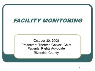
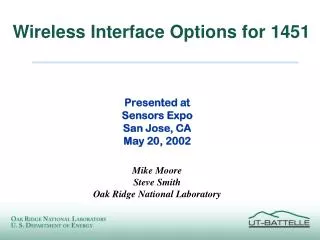
Presented by: Marin Marinov, Todor Djamiykov, Georgi Nikolov, Dimitar Alexiev E-mail:mbm@tu-sofia.bg FacilityMonitoring System with IEEE 1451 Interface
Raising cost of energy in recent years. Rapid growth and interest in building more sustainable and healthier buildings. Interest in building facilities to be more energy efficient while also enhancing a facility’s indoor environmental quality (IEQ). 1. Introduction
One of the major reasons for this shortcut occurs is that the quality, accuracy, and quantity of indoor environmental sensors that are typically used are not sufficient to successfully and cost effectively implement many of the energy efficiency approaches. Even more often, information about the quality of the indoor environment is not sensed at all due to the cost of doing so, leading to situations where systems do not properly control, resulting in complaints, and subsequent disabling of the control approaches, and finally the loss of the expected energy savings. 1. Introduction
To enable effective energy savings applications such as demand controlled ventilation, a multi-parameter, multiple location, facility monitoring system should be implemented, which meets at the following requirements: Facility Monitoring System Requirements: Low first equipment and installation cost per parameter (for different locations), Low maintenance and calibration costs, Possibility for sensing a broad range of (indoor) environmental parameters & air contaminants, Satisfactory accuracy and long term stability. 2. Requirements for a effective Facility Monitoring System
Indoor air parameters such as temperature, humidity, carbon dioxide and other parameters have traditionally been sensed by wiring individual air parameter sensors into a building management system (BMS). This works fine for simple, inexpensive and reliable sensors such as temperature sensors. However, building monitoring requirements for indoor air parameters have increased so that many locations need to be monitored for other parameters such as: relative humidity, dewpoint temperature, carbon dioxide (CO2), carbon monoxide (CO), total volatile organic compounds (TVOCs), odors, fine particles, etc. 3. Traditional Approaches to Sensing Air Parameters in a Facility
Problems with Traditional Sensor Approaches High First Cost Many sensors required for multiple parameter, multiple location sensing First cost to sense many parameters quickly becomes too high Commercial grade sensors often used, causing poor accuracy & reliability High cost of installation & integration A single hard wired Building Management System CO2 or RH point can range from: € 500 to € 1000/pt. 3. Traditional Approaches to Sensing Air Parameters in a Facility
Problems with Traditional Sensor Approaches High Operating Costs Accuracy required often beyond sensor limits Poor performance results = Lost energy savings High maintenance cost Every sensor needs periodic calibration (1x - 4x/yr) 3. Traditional Approaches to Sensing Air Parameters in a Facility
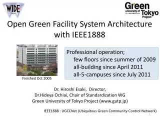
IEEE 1451 Standard for Smart Transducer The IEEE 1451 Standard provides a set of common interfaces for connecting sensors and actuators to existing instrumentation and control networks and lays a path for the sensor community to design systems for future growth. It is intended to provide an easy upgrade path for connectivity of products from any manufacturer of transducers or networks. The IEEE 1451 Standard can be basically viewed as a software and hardware oriented interfaces. 4. The IEEE 1451 Approach for Sensing Air Parameters
IEEE 1451 Standard for Smart Transducer The software portion is an information model defining the behaviors of a smart transducer using object model approach and the path for network connectivity. This work has been completed and become the IEEE 1451.1 Standard. The sensor usage crosses various industries, therefore the hardware portion of the IEEE 1451 Standard is divided into 1451.2, 1451.3, 1451.4, 1451.5 etc. 4. The IEEE 1451 Approach for Sensing Air Parameters
IEEE 1451.4 Network-Capable Application Processor (NCAP) Analog + Digital Mixed-Mode Transducer 10 0 2 2 or 4 IEEE 1451.2 Any Network TEDS Txdcr Digital, Point-to-Point Smart Transducer Interface Module (STIM) Digital TII Interface IEEE 1451.1 Common Object Model IEEE P1451.0 Common Function-ality & TEDS IEEE 1451.3 Distributed Multidrop Bus Transducer Bus Interface Module (TBIM) Txdcr Bus Interface TEDS TEDS TEDS IEEE 1451.5 A/D A/D A/D Txdcr Txdcr Txdcr Wireless Wireless Transducer Wireless Interface IEEE 1451 Standards - Another View TXdcr = Transducer (Sensor or Actuator)
Web Based Virtual TEDS database NI Plug & Play Sensor Partner Program Backwards Compatibility Collaboration Multi-Vendor Smart TEDS Sensors IEEE P1451.4 System Integration Sensors NI Alliance Partners Measurement Hardware Communicate to End-Users Web Based Plug and Play Sensor Advisor Development Kit Programming Software TEDS LabVIEW Library 5. IEEE 1451.4 Mixed-ModeTransducer Broad-Based Industry Adoption TEDS LabVIEW Library
The drive for transducers with built-in identification, manufacture data such as calibration, and extended functionality has increased sharply over the last years. The transducer community, started the work on the IEEE 1451.4 standard to meet the demands and needs of the changing industry. 5. IEEE 1451.4 Mixed-ModeTransducer
The main objectives of the proposed standard are to: Enable plug and play at the transducer level by providing a common communication interface compatible with conventional transducers. Enable and simplify the creation of smart transducers. Facilitate the support of multiple networks. Make a bridge between the conventional transducers and the networked transducers. 5. IEEE 1451.4 Mixed-ModeTransducer
5. IEEE 1451.4 Mixed-ModeTransducer Basic Architecture IEEE 1451.4 - Mixed-Mode Communication Interface (MMI) and Transducer Electronic Data Sheet (TEDS)
5. IEEE 1451.4 Mixed-ModeTransducer IEEE 1451.4 Transducer Electronic Data Sheet (TEDS) (Dot 4 TEDS) • UUID (Universal Unique Identifier) • Supplied by EEPROM (DS2433) manufacturer (6 bytes) • Basic TEDS (8 bytes) • Model Number (15 bits) • Version Letter (5 bits, A-Z) • Version Number (6 bits) • Manufacturer ID (14 bits) • Serial Number (6 bits) • Manufacturer’s TEDS • Sensor type and calibration parameters (16 bytes)
6. IEEE 1451.4 Gas Sensors Implementation Basic Architecture
6. IEEE 1451.4 Gas Sensors Implementation System overview • Prototype based on an 8-bit microcontroller (PIC16F87х) from Microchip • TEDS – 4k EEPROM (DS2433) • Main advantages : • Single power supply (+5 /12 V), • Reduced power consumption, • Low cost, • Self-calibration capability.
6. IEEE 1451.4 Gas Sensors Implementation Plug-in Module as IEEE 1451.4 – Class 2 Multi-Wire Gas Sensor
6. IEEE 1451.4 Gas Sensors Implementation Signal conditioner • The signal conditioning circuit (for the sensor resistance) is based on a • voltage divider connected to the ADC microcontroller input through a low-pass filter and • amplifier featuring a high input impedance.
6. IEEE 1451.4 Gas Sensors Implementation Basic microcontroller module
6. IEEE 1451.4 Gas Sensors Implementation Microcontroller module with differentt Plug-in modules
Detection of gases or vapors in air is becoming important mainly in the context of energy efficiency, safety and environment control. In the last 10 years a great effort is applied to realize low-cost, compact instruments that can detect the presence of chemical compounds and pollutants. Embedded with a microcontroller unit the smart sensor have much more built-in intelligence over the traditional sensors. So they can perform more intelligent functions such as: Self-identification, Self adaptation, Self-calibration etc. Conclusion
One of the most attractive advantages that a smart sensor offers is the networking capability defined by the IEEE 1451 smart transducer interface family of standards. One of the basic aims of this standards is to support the implementation of plug and play functionality at the sensor/actuator level, standardizing data structures and communication. The development of a gas sensor system with inter-changeable sensor heads which can be used with a variety of sensor technologies was presented. By the implementation IEEE 1451.4 TEDS for automatic configuration of the sensor heads was used. Conclusion
The support of Contract # 09NI044-03 NIS - TU Sofia and AiF Contract # 1841-04-329 is acknowledged. ACKNOWLEDGMENT