Download
1 / 63
660 likes | 890 Views
CHAPTER 19 Vibration and Noise Diagnosis and Correction. OBJECTIVES. After studying Chapter 19, the reader will be able to: Prepare for Suspension and Steering (A4) ASE certification test content area “C” (Related Suspension and Steering Service).

E N D
CHAPTER 19 Vibration and Noise Diagnosis and Correction
OBJECTIVES After studying Chapter 19, the reader will be able to: • Prepare for Suspension and Steering (A4) ASE certification test content area “C” (Related Suspension and Steering Service). • Discuss how to perform a road test for vibration and noise diagnosis. • List the possible vehicle components that can cause a vibration or noise. • Describe the use of a reed tachometer or electronic vibration analyzer in determining the frequency of the vibration. • Discuss the procedures used in measuring and correcting driveshaft angles.
Companion Flange Driveline Angles Driveshaft Runout EVA Frequency Hertz (Hz) Neutral Run-up Test NVH Rolling Circumference Vibration Order Witness Mark KEY TERMS
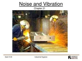
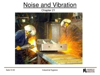
INTRODUCTION • Vibration and noise are two of the most frequent complaints from vehicle owners and drivers. • If something is vibrating, it can move air; changes in air pressure (air movement) are what we call noise. • Though anything that moves vibrates, wheels and tires account for the majority of vehicle vibration problems.
CAUSES OF VIBRATION AND NOISE • Vehicles are designed and built to prevent most vibrations and to dampen out any vibrations that cannot be eliminated. • For example, engines are designed and balanced to provide smooth power at all engine speeds. • Some engines, such as large four-cylinder or 90-degree V-6’s, require special engine mounts to absorb or dampen any remaining oscillations or vibrations. • Dampening weights are also fastened to engines or transmissions in an effort to minimize noise, vibration, and harshness (called NVH).
FIGURE 19–1 Many vehicles, especially those equipped with four-cylinder engines, use a dampener weight attached to the exhaust system or differential as shown to dampen out certain frequency vibrations. CAUSES OF VIBRATION AND NOISE
FIGURE 19–2 The exhaust was found to be rubbing on the frame rail during a visual inspection. Rubber exhaust system hangers are used to isolate noise and vibration from the exhaust system from entering the interior. These rubber supports can fail causing the exhaust system to be out of proper location. It was found by looking for evidence of witness marks. CAUSES OF VIBRATION AND NOISE
TEST DRIVE • The first thing a technician should do when given a vibration or noise problem to solve is to duplicate the condition. • This means the technician should drive the vehicle and observe when and where the vibration is felt or heard. • Though there are many possible sources of a vibration, some simple observations may help to locate the problem quickly: • If the vibration is felt or seen in the steering wheel, dash, or hood of the vehicle, the problem is most likely to be caused by defective or out-of-balance front wheels or tires. • If the vibration is felt in the seat of the pants or seems to be all over the vehicle, the problem is most likely to be caused by defective or out-of-balance rear wheels or tires.
FIGURE 19–3 A chart showing the typical vehicle and engine speeds at which various components will create a noise or vibration and under what conditions. (Courtesy of Dana Corporation) TEST DRIVE
FIGURE 19–4 Vibration created at one point is easily transferred to the passenger compartment. MacPherson strut suspensions are more sensitive to tire imbalance than SLA-type suspensions. TEST DRIVE
NEUTRAL RUN-UP TEST • The neutral run-up test is used to determine if the source of the vibration is engine-related. • With the transmission in Neutral or Park, slowly increase the engine RPM and with a tachometer observe the RPM at which the vibration occurs. • DO NOT EXCEED THE MANUFACTURER’S RECOMMENDED MAXIMUM ENGINE RPM. • If the fault is found in the engine itself, further engine testing is needed to find the root cause.
VIBRATION DURING BRAKING • A vibration during braking usually indicates out-of-round brake drums, warped disc brake rotors, or other braking system problems. • The front rotors are the cause of the vibration if the steering wheel is also vibrating (moving) during braking. • The rear drums or rotors are the cause of the vibration if the vibration is felt throughout the vehicle and brake pedal, but not the steering wheel. • Another way to check if the vibration is due to rear brakes is to use the parking brake to stop the vehicle. • If a vibration occurs while using the parking brake, the rear brakes are the cause.
The Duct Tape Trick • A clicking noise heard at low speeds from the wheels is a common noise complaint. This noise is usually most noticeable while driving with the windows lowered. This type of noise is caused by loose disc brake pads or noisy wheel covers. Wire wheel covers are especially noisy. To confirm exactly what is causing the noise, simply remove the wheel covers and drive the vehicle. If the clicking noise is still present, check the brakes and wheels for faults. If the noise is gone with the wheel covers removed, use duct tape over the inner edge of the wheel covers before installing them onto the wheels. The duct tape will cushion and dampen the wheel cover and help reduce the noise. The sharp prongs of the wheel cover used to grip the wheel will pierce through the duct tape and still help retain the wheel covers.
S-10 Pickup Truck Frame Noise • The owner of a Chevrolet S-10 pickup truck complained of a loud squeaking noise, especially when turning left. Several technicians attempted to solve the problem and replaced shock absorbers, ball joints, and control arm bushings without solving the problem. The problem was finally discovered to be the starter motor hitting the frame. A measurement of new vehicles indicated that the clearance between the starter motor and the frame was about 1/8 in. (0.125 in.) (0.3 cm)! The sagging of the engine mount and the weight transfer of the engine during cornering caused the starter motor to rub up against the frame. The noise was transmitted through the frame throughout the vehicle and made the source of the noise difficult to find.
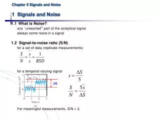
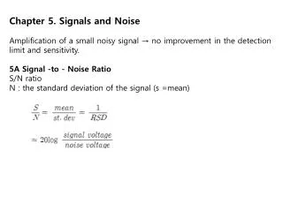
VIBRATION SPEED RANGES • Vibration describes an oscillating motion around a reference position. • The number of times a complete motion cycle takes place during a period of 1 second is called frequency and is measured in hertz (Hz) (named for Heinrich R. Hertz, a nineteenthcentury German physicist).
FIGURE 19–5 Hertz means cycles per second. If six cycles occur in 1 second, then the frequency is 6 Hz. The amplitude refers to the total movement of the vibrating component. (Courtesy of Hunter Engineering Company) VIBRATION SPEED RANGES
FIGURE 19–6 Every time the end of a clamped yardstick moves up and down, it is one cycle. The number of cycles divided by the time equals the frequency. If the yardstick moves up and down 10 times (10 cycles) in 2 seconds, the frequency is 5 Hertz (10/2 = 5). (Courtesy of Hunter Engineering Company) VIBRATION SPEED RANGES
VIBRATION SPEED RANGES • VIBRATION ORDER • TIRE AND WHEEL VIBRATIONS • LOW FREQUENCY (5–20 HZ) • DRIVELINE VIBRATIONS • MEDIUM FREQUENCY (20–50 HZ) • ENGINE-RELATED VIBRATIONS • HIGH FREQUENCY (50–100 HZ)
FIGURE 19–7 Determining the rolling circumference of a tire. VIBRATION SPEED RANGES
The Vibrating Van • After the engine was replaced in a rear-wheel-drive van, a vibration that felt like an engine miss was noticed by the driver. Because the vibration was not noticed before the engine was replaced, the problem was thought to be engine-related. Many tests failed to find anything wrong with the engine. Even the ignition distributor was replaced, along with the electronic ignition module, on the suspicion that an ignition misfire was the cause. • After hours of troubleshooting, a collapsed transmission mount was discovered. After replacing the transmission mount, the “engine miss” and the vibration were eliminated. The collapsed mount caused the driveshaft U-joint angles to be unequal, which caused the vibration.
FIGURE 19–8 An electronic vibration analyzer. FREQUENCYMEASURING FREQUENCY • Knowing the frequency of the vibration greatly improves the speed of tracking down the source of the vibration. • Vibration can be measured using a reed tachometer or an electronic vibration analyzer (EVA).
FREQUENCYCORRECTING LOW-FREQUENCY VIBRATIONS • A low-frequency vibration (5–20 Hz) is usually due to tire/wheel problems, including the following: • Tire and/or wheel imbalance. • Tire and/or wheel radial or lateral runout. • Radial force variation within the tire itself. • If front-wheel drive, a bent or damaged drive axle joint or shaft. • Warped rotors.
FIGURE 19–9 Properly balancing all wheels and tires solves most low-frequency vibrations. FREQUENCYCORRECTING LOW-FREQUENCY VIBRATIONS
FIGURE 19–10 An out-of-balance tire showing scallops or bald spots around the tire. Even if correctly balanced, this cupped tire would create a vibration. FREQUENCYCORRECTING LOW-FREQUENCY VIBRATIONS
FIGURE 19–11 Another cause of a vibration that is often blamed on wheels or tires is a bent bearing hub. Use a dial indicator to check the flange for runout. FREQUENCYCORRECTING LOW-FREQUENCY VIBRATIONS
FREQUENCYCORRECTING MEDIUM-FREQUENCY VIBRATIONS • Medium-frequency vibrations (20–50 Hz) can be caused by imbalances of the driveline as well as such things as the following: • Defective U-joints. Sometimes an old or a newly installed U-joint can be binding. This binding of the U-joint can cause a vibration. Often a blow to the joint with a brass hammer can free a binding U-joint. This is often called relieving the joint. Tapping the joint using a brass punch and a hammer also works well. • Driveshaft imbalance (such as undercoating on the driveshaft) or excessive runout. • Incorrect or unequal driveshaft angles.
FREQUENCYCORRECTING HIGH-FREQUENCY VIBRATIONS • Highfrequency vibrations (50–100 Hz) are commonly caused by a fault of the clutch, torque converter, or transmission main shaft that rotates at engine speed; in the engine itself, they can be caused by items such as the following: • A defective spark plug wire • A burned valve • Any other mechanical fault that will prevent any one or more cylinders from firing correctly • A defective harmonic balancer
Squeaks and Rattles • Many squeaks and rattles commonly heard on any vehicle can be corrected by tightening all bolts and nuts you can see. Raise the hood and tighten all fender bolts. Tighten all radiator support and bumper brackets. Open the doors and tighten all hinge and body bolts. • An even more thorough job can be done by hoisting the vehicle and tightening all under-vehicle fasteners, including inner fender bolts, exhaust hangers, shock mounts, and heat shields. It is amazing how much this quiets the vehicle, especially on older models. It also makes the vehicle feel more solid with far less flex in the body, especially when traveling over railroad crossings or rough roads.
CORRECTING DRIVELINE ANGLES • Incorrect driveline angles are usually caused by one or more of the following: • Worn, damaged, or improperly installed U-joints. • Worn, collapsed, or defective engine or transmission mount(s). • Incorrect vehicle ride height. (As weight is added to the rear of a rear-wheel-drive vehicle, the front of the differential rises and changes the working angle of the rear U-joint.) • Bent or distorted driveshaft.
CHECKING DRIVESHAFT RUNOUT • Check to see that the driveshaft is not bent by performing a driveshaft runout test using a dial indicator. • Runout should be measured at three places along the length of the driveshaft. • The maximum allowable runout is 0.030 in. (0.76 mm). • If runout exceeds 0.030 in., remove the driveshaft from the rear end and reindex the driveshaft onto the companion flange at 180 degrees from its original location. • Remeasure the driveshaft runout. • If the runout is still greater than 0.030 in., the driveshaft is bent and needs replacement or the companion flange needs replacement.
MEASURING DRIVESHAFT U-JOINT PHASING • Measuring driveshaft U-joint phasing involves checking to see if the front and rear U-joints are directly in line or parallel with each other. • With the vehicle on a drive-on lift, or if using a framecontact hoist, support the weight of the vehicle on stands placed under the rear axle. • Place an inclinometer on the front U-joint bearing cup and rotate the driveshaft until horizontal; note the inclinometer reading.
MEASURING DRIVESHAFT U-JOINT PHASING • Move the inclinometer to the rear U-joint. • The angles should match. • If the angles are not equal, the driveshaft is out of phase and should be replaced. • Incorrect phasing is usually due to a twisted driveshaft or an incorrectly welded end yoke.
COMPANION FLANGE RUNOUT • The companion flange is splined to the rear axle pinion shaft and provides the mounting for the rear U-joint of the driveshaft. • Two items should be checked on the companion flange while diagnosing a vibration: • The companion flange should have a maximum runout of 0.006 in. (0.15 mm) while being rotated. If the flange was pounded off with a hammer during a previous repair, the deformed flange could cause a vibration. • Check the companion flange for a missing balance weight. Many flanges have a balance weight that is spot-welded onto the flange. If the weight is missing, a driveline vibration can result.
BALANCING THE DRIVESHAFT • If the driveshaft (propeller shaft) is within runout specification and a vibration still exists, the balance of the shaft should be checked and corrected as necessary. • Checking for driveshaft balance is usually done with a strobe balancer. • The strobe balancer was commonly used to balance tires on the vehicle and was very popular before the universal use of computer tire balancers. • A strobe balancer uses a magnetic sensor that is attached to the pinion housing of the differential. • The sensor causes a bright light to flash (strobe) whenever a shock force is exerted on the sensor.
FIGURE 19–12 When checking the balance of a driveshaft, make reference marks around the shaft so that the location of the unbalance may be viewed when using a strobe light. BALANCING THE DRIVESHAFT
FIGURE 19–13 Using a strobe balancer to check for driveline vibration requires that an extension be used on the magnetic sensor. Tall safety stands are used to support the rear axle to keep the driveshaft angles the same as when the vehicle is on the road. BALANCING THE DRIVESHAFT
FIGURE 19–14 Typical procedure to balance a driveshaft using hose clamps. BALANCING THE DRIVESHAFT
FIGURE 19–15 Two clamps were required to balance this front driveshaft of a four-wheel-drive vehicle. Be careful when using hose clamps that the ends of the clamps do not interfere with the body or other parts of the vehicle. BALANCING THE DRIVESHAFT
Everything Is OK until I Hit a Bump • The owner of an eight-year-old vehicle asked that the vibration in the steering wheel be repaired. It seemed that the vehicle drove fine until the front wheels hit a bump in the road—then the steering wheel shimmied for a few seconds. • This problem is typical of a vehicle with excessive steering linkage freeplay. When driving straight, centrifugal (rolling) force on the tires tends to force the front wheels outward (toe-out). When one or both wheels hit a bump, the play in the linkage becomes apparent, causing the steering wheel to shimmy until the rolling force again equalizes the steering.
Everything Is OK until I Hit a Bump • The service technician performed a test drive and a careful steering system inspection and discovered freeplay in both inner tie rod end sockets of the rack-and-pinion unit. The steering unit also had some power steering leakage at the tie rod bellows. A replacement remanufactured power-rack-andpinion steering unit was recommended to the customer. The customer approved the replacement rack and authorized the required realignment. A careful test drive confirmed that the problem was corrected.
NOISE DIAGNOSIS • Noise diagnosis is difficult because a noise is easily transmitted from its source to other places in the vehicle. • For example, if a rear shock absorber mount is loose, the noise may be heard as coming from the middle or even the front of the vehicle. • As the axle moves up and down, the noise is created where metal touches metal between the shock absorber bolt and the axle shock mount.
NOISE DIAGNOSIS • The noise is then transmitted throughout the frame of the vehicle, and therefore causes the sound to appear to come from “everywhere.” • To help pin down the exact location of the sound, perform a thorough test drive, including driving beside parked vehicles or walls with the vehicle windows open.
FIGURE 19–16 Tire wear caused by improper alignment or driving habits, such as high-speed cornering, can create tire noise. Notice the feather-edged outer tread blocks. NOISE DIAGNOSIS
FIGURE 19–17 This bearing was found on a vehicle that had been stored over the winter. This corroded bearing produced a lot of noise and had to be replaced. NOISE DIAGNOSIS
FIGURE 19–18 An inner race from an input shaft bearing. This bearing caused the five-speed manual transmission to be noisy in all gears except fourth gear. In fourth gear, the torque is transferred straight through the transmission, whereas in all other gears the torque is applied to the countershaft that exerts a side load to the input bearing. NOISE DIAGNOSIS
RAP It • Many technicians who service transmissions and differentials frequently replace all bearings in the differential when there is a noise complaint. While this at first may seem to be overkill, these technicians have learned that one defective bearing may put particles in the lubricant, often causing the destruction of all the other bearings. This practice has been called RAP (replace all parts), and in the case of differentials, RAP may not be such a bad idea.
NOISE CORRECTION • The proper way to repair a noise is to repair the cause. • Other methods that have been used by technicians include the following: • Insulating the passenger compartment to keep the noise from the passengers. • Turning up the radio!
Engine Noise • An experienced technician was assigned to diagnose a loud engine noise. The noise sounded like a defective connecting rod bearing or other major engine problem. The alternator belt was found to be loose. Knowing that a loose belt can “whip” and cause noise, the belt was inspected and the alternator moved on its adjustment slide to tighten the belt. After tightening the belt, the engine was started and the noise was still heard. After stopping the engine, the technician found that the alternator belt was still loose. The problem was discovered to be a missing bolt that attached the alternator mounting bracket to the engine. The forces on the alternator caused the bracket to hit the engine. This noise was transmitted throughout the entire engine. Replacing the missing bracket bolt solved the loud engine noise and pleased a very relieved owner.