Download
1 / 13
130 likes | 248 Views
From L1Calo to S-L1Calo. algorithms – architecture - technologies. L1Calo S-L1Calo phase1 phase2. phase1: do not modify PPr – JEM – CPM replace CMMs by something new add a global calorimeter trigger processor close to the CTP phase2: assume different type of off-detector links

E N D
From L1Calo to S-L1Calo algorithms – architecture - technologies
L1Calo S-L1Calo phase1 phase2 • phase1: • do not modify PPr – JEM – CPM • replace CMMs by something new • add a global calorimeter trigger processor close to the CTP • phase2: assume • different type of off-detector links • different granularity • replace L1Calo • integrate CTP and global calorimeter trigger ???
what we need... ... some hardware to receive trigger information from the calorimeters and run trigger algorithms with improved background suppression and rate capability. However: • upstream interfaces not yet defined • detailed algorithms not yet known Nevertheless, we need to start work on a concept now : • adequate physics performance • scalable • reliable (signal integrity) • advanced (but not exotic) technologies • simple scheme • small number of different module types • commonly used COTS • industry standard protocols and form factors • affordable, but not cheap
what we got:current L1Calo - algorithms and architecture • feature extraction: calculate global variables and identify localized objects by sliding window algorithm :jets, e/gamma, tau • feature reduction : Count objects passing energy thresholds • feature correlation not included on L1Calo Implementation: • 5 stages (in terms of data reception / processing / re-transmission): • JEM/CPM : fan-out and sliding windows/threshold/count • 2-stage merging (CMM) • final stage of feature correlation offloaded to CTP (incl. muons) • electrical data transmission: serial and parallel • fan-out via • upstream link replication 38%(JEP), 25%(CP) in phi direction • backplane re-transmission : 75%, in eta direction
S-L1Calo - algorithms and architecture future system conceptionally very similar: • feature extraction: calculate global variables and identify localized objects by sliding window algorithm • jets • e/gamma • tau • feature reduction : drop objects of least significance ? • feature correlation Implementationmight also be similar to L1calo, but could be more compact, in smaller number of stages: • jet/cluster module (JCM) covering feature extraction (jets, e/, ) and possibly some feature reduction • GCT CTP Optical data transmission only o/e processor e/o
data transmission and fan-out scheme • go optical • keep fan-out simple and avoid latency penalty: • upstream optical link replication • excellent signal integrity • additional optical components required • cost effective for low replication factors only it pays to go for highest density / highest link speed • downstream electrical link replication • signal integrity depends on backplane and connectors • additional de-serializers • very cost effective(multi – Gb/s links cheap) • avoid re-transmissionon the backplane (serdes latency) source source source e/o e/o e/o o/e o/e sink sink e/o e/o
technologies The need for high bandwidth data transmission, in particular for network processor applications, has brought us new and improved standards on paper and on silicon. • link speeds on existent high volume products scaling up (SAS2.0/SATA3.0 @ 6 Gb/s electrical) • network processor protocols (Interlaken / SPAUI / SPI-S) build on scalable high speed link definitions OIF-CEI-6G, -11G, -25G • FPGA on-chip links currently support up to 48 CEI-6G lanes (ie. aggregate bandwidth of 36 Gigabyte/s per FPGA) • parallel opto links (SNAP12/MSA) are available up to 10Gb/s per lane • low power (~1W) mid-board mount SNAP12 devices (fibre pig-tail) move O/E converters away from board edge so as to improve density, routability and signal integrity • AdvancedTCA allows to route 10Gb/s lanes on a backplane
... and how about phase1 ??? while the sliding window processor will stay as is ... • try to extract largest possible volume of features from the processors via merger interface • think about moderate feature reduction at crate level • consider one-stage feature correlation integrating global calorimeter trigger and CTP • for everything else just follow the same lines:choice of components, opto transmission, link replication, data rate / board density considerations...
phase 1 – the algorithms ??? • due to moderate feature reduction (or no reduction at all) full topological information will be available at the CTP* • we should define what topologies we want to explore • features within the same solid angle • back-to-back topology • ????? please have ideas and simulate them ! • please remember that all information we want to correlate needs to end up on the same processor chip some further level of link replication and fibre patching might be required to get the data where needed *) for CTP read : central trigger processor or global calorimeter trigger processor (in case we do not want to re-do the CTP). A re-designed CTP might be preferred, so as to better correlate with muons.
Motivation: Pileup @SLHC: ~400 interactions per BX (50 ns bunchspacing and 1035s-1cm-2) • degradationofalgorithmperformance • compensationbymore granular data (Phase 2) „granularity vs. environment“ size and/orrefinedalgorithms (Phase 1 & 2) Possible selection criteria on L1 by using RoI information on CTP level: • exclusive trigger combinations beyond multiplicity combination: distinct separation between em and jets at different thresholds • Azimuthal “back-to-back” criteriae.g. Selection of Higgs production • Forward-Backward correlation in rapidity gap in ηe.g. VBF processes • definition of isolated muons by using calorimeter energy • tagging of b-jets by soft muons • calculation of mass/transversal mass of object pairs or even more objects • Etmiss correction by using pT of muons, identification of jets directing to cracks or Etmiss Relatively straightforward Level ofdifficulty complex
R&D road map • get some further input on suitable algorithms • let’s try and follow industry standard electrical and optical component development • decide on development platform soon: ATCA/TCA ? • phase 1 : 6Gb/s technology is here today and can be used out of the box • phase 2 : expect further increase in density and data rates. Make use of it. • be warned : attractive technologies are attractive to big buyers even more. Component availability is a problem already now. Lead time for SNAP12 devices (irrespective of data rate) is currently 20-30 weeks !
example : re-do current system • assume unchanged pre-processing (including BCmux), but optical links from the PPr to the digital processors • total cluster and jet input data volume is roughly4 [crates] * (14+2) [slots] * 64 channels = 4096 channels 1640 Gb/s 288 fibres @ 5.6Gb/s total data volume will fit on 8 modules with just three SNAP12 devices each. • though the links would easily fit on a single FPGA per module, the design is likely to be logic capacity bound. Use several FPGAs per board, with high capacity and few links • each module could process full phi range and 8 eta bins. Overlap would be 6 eta bins downstream link duplication only. • we can easily end up with a two-stage system of JCMs sending data directly to a single module Global Calorimeter Processor that can be integrated with the CTP which connects up muons
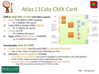
The implementation... Advanced TCA XC5VFX100T – FF1136 SNAP12 : ICT75GVX1361 CML or PECL fanout