Download
1 / 29

E N D
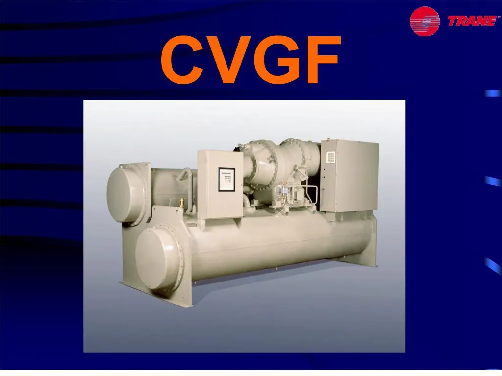
1. CVGF
2. Back to the basics
Why Trane developed the CVGF ?
Market position
Mechanical operation
Complementary information
Planning
4. Fundamentally, centrifugal chillers perform the same function as the familiar reciprocating machines. However, the thing that sets the centrifugal chiller apart is the means used to compress the refrigerant gas.
Comparatively, the reciprocating compressor is a positive displacement machine. On the intake stoke of the piston, a quantity of gas fills the cylinder.
And, on the compression stroke the gas is compressed and discharged from the cylinder.
Discounting inefficiency, the quantity of gas pumped by each stoke of the piston equals the cubic displacement of the cylinder.Fundamentally, centrifugal chillers perform the same function as the familiar reciprocating machines. However, the thing that sets the centrifugal chiller apart is the means used to compress the refrigerant gas.
Comparatively, the reciprocating compressor is a positive displacement machine. On the intake stoke of the piston, a quantity of gas fills the cylinder.
And, on the compression stroke the gas is compressed and discharged from the cylinder.
Discounting inefficiency, the quantity of gas pumped by each stoke of the piston equals the cubic displacement of the cylinder.
5. The centrifugal compressor, on the other hand, uses dynamic compression, which involves energy conversion, to achieve the same end.
The first law of thermodynamic states: energy is neither destroyed nor created in the process of conversion from one to another.
Keeping this in mind, the energy conversion that takes place within the centrifugal compressor will be discussed.
The operating member of a centrifugal compressor is the impeller. The center, or eye, of the impeller is fitted with vanes that draw gas into radial passages which are internal to the impeller body. Impeller rotation accelerates the gas within these passages, imparting to it kinetic energy or the energy of motion.
As the gas flows trough the compressor, the volume of gas passages available for gas flow increases. As the gas fills this increasing space, its velocity reduces. And, as the velocity is reduced, the kinetic energy, or energy of motion, is not destroyed, instead it is converted to static energy or static pressure.
This series of events conforms to the previously cited thermodynamic law which, put another way, states: energy cannot be destroyed however it can be it can be converted from one for to another.
The centrifugal compressor, on the other hand, uses dynamic compression, which involves energy conversion, to achieve the same end.
The first law of thermodynamic states: energy is neither destroyed nor created in the process of conversion from one to another.
Keeping this in mind, the energy conversion that takes place within the centrifugal compressor will be discussed.
The operating member of a centrifugal compressor is the impeller. The center, or eye, of the impeller is fitted with vanes that draw gas into radial passages which are internal to the impeller body. Impeller rotation accelerates the gas within these passages, imparting to it kinetic energy or the energy of motion.
As the gas flows trough the compressor, the volume of gas passages available for gas flow increases. As the gas fills this increasing space, its velocity reduces. And, as the velocity is reduced, the kinetic energy, or energy of motion, is not destroyed, instead it is converted to static energy or static pressure.
This series of events conforms to the previously cited thermodynamic law which, put another way, states: energy cannot be destroyed however it can be it can be converted from one for to another.
6. The forces that act on the gas within the impeller can be broken down into two components. One component force acts to move the gas away from the impeller in a radial direction. This is the radial velocity component (Vr).
The second force acts to move the gas in the direction of the impeller rotation. This the tangential velocity component (Vt).
Both of these forces act to generate the resultant velocity vector (R), the length of which is proportional to the kinetic energy available for conversion to static pressure.
The forces that act on the gas within the impeller can be broken down into two components. One component force acts to move the gas away from the impeller in a radial direction. This is the radial velocity component (Vr).
The second force acts to move the gas in the direction of the impeller rotation. This the tangential velocity component (Vt).
Both of these forces act to generate the resultant velocity vector (R), the length of which is proportional to the kinetic energy available for conversion to static pressure.
7. It should be noted that the radial velocity component (Vr) is directly proportional to the gas flow. The tangential velocity component is proportional to the impeller rotational speed times the impeller diameter.
Therefore, the static pressure producing capability of a compressor can be adjusted by changing the gas flow, impeller speed or impeller diameter.
Since the tangential velocity component (Vt) is proportional to the impeller speed times diameter, this change increases the length of this component force, resulting in a longer resultant velocity vector (R). Recall, the length of this vector is proportional to the kinetic energy available for conversion to static pressure. However, since the gas flow handled by the compressor remains unchanged, the radial velocity component (Vr) similarly remains unchanged.
The significance of this is, with an increased tangential velocity component. This compressor is capable of developing higher static pressures.
This can present a problem when the load decreases, resulting in a reduced gas flow rate. It should be noted that the radial velocity component (Vr) is directly proportional to the gas flow. The tangential velocity component is proportional to the impeller rotational speed times the impeller diameter.
Therefore, the static pressure producing capability of a compressor can be adjusted by changing the gas flow, impeller speed or impeller diameter.
Since the tangential velocity component (Vt) is proportional to the impeller speed times diameter, this change increases the length of this component force, resulting in a longer resultant velocity vector (R). Recall, the length of this vector is proportional to the kinetic energy available for conversion to static pressure. However, since the gas flow handled by the compressor remains unchanged, the radial velocity component (Vr) similarly remains unchanged.
The significance of this is, with an increased tangential velocity component. This compressor is capable of developing higher static pressures.
This can present a problem when the load decreases, resulting in a reduced gas flow rate.
8. Since the radial velocity component is proportional to gas flow, its balancing force drops. And, at some point, the balance of force breaks down, allowing pressurized gas to flow back into the impeller. The instantaneously reduces the pressure within the gas passages, allowing the compressor to re-establish the original balance of forces. So long as this unstable condition exists, gas pulsation continues.
This is a condition known as surge. Surge results in inefficiency, static pressure fluctuation, vibration and noise.
To stabilize compressor performance over a range of load conditions (gas flow rates), inlet vanes are installed ahead of the compressor.
Inlet vanes function to adjust the gas quantity as well as the angle at which the gas enters the impeller, creating a new compressor performance characteristic with each vane position.Since the radial velocity component is proportional to gas flow, its balancing force drops. And, at some point, the balance of force breaks down, allowing pressurized gas to flow back into the impeller. The instantaneously reduces the pressure within the gas passages, allowing the compressor to re-establish the original balance of forces. So long as this unstable condition exists, gas pulsation continues.
This is a condition known as surge. Surge results in inefficiency, static pressure fluctuation, vibration and noise.
To stabilize compressor performance over a range of load conditions (gas flow rates), inlet vanes are installed ahead of the compressor.
Inlet vanes function to adjust the gas quantity as well as the angle at which the gas enters the impeller, creating a new compressor performance characteristic with each vane position.
9. These curves represent the performance characteristics of a typical single-stage compressor over a range of inlet vane positions. The pressure differences between the inlet (evaporator) and outlet (condenser) of the compressor are on the vertical axis. The compressor gas flow capabilities at the various pressure differences and vane positions are on the horizontal axis. The broken line represents the gas flow and pressure difference conditions that produce surge. Any compressor operating point that falls to the right of this line is satisfactory from a stability stand point.These curves represent the performance characteristics of a typical single-stage compressor over a range of inlet vane positions. The pressure differences between the inlet (evaporator) and outlet (condenser) of the compressor are on the vertical axis. The compressor gas flow capabilities at the various pressure differences and vane positions are on the horizontal axis. The broken line represents the gas flow and pressure difference conditions that produce surge. Any compressor operating point that falls to the right of this line is satisfactory from a stability stand point.
10. Assume to balance a building design load, the compressor must pump a certain flow of refrigerant gas of a certain temperature and pressure from the evaporator and elevate its pressure to that dedicated by the condensing conditions.
Locating the required flow on the horizontal axis and the pressure difference between the compressor inlet and outlet on the vertical axis of the same grid used previously to describe compressor performance, the point where lines projected from these coordinates intersect identifies the system full load operating point.Assume to balance a building design load, the compressor must pump a certain flow of refrigerant gas of a certain temperature and pressure from the evaporator and elevate its pressure to that dedicated by the condensing conditions.
Locating the required flow on the horizontal axis and the pressure difference between the compressor inlet and outlet on the vertical axis of the same grid used previously to describe compressor performance, the point where lines projected from these coordinates intersect identifies the system full load operating point.
11. These curves represent the performance of a typical 2 stage and 1 stage centrifugal compressor. As before, the pressure differences between the compressor inlet and outlet are on the vertical axis and the compressor gas flow capability at various pressures differences and vane positions are on the horizontal axis.
These curves represent the performance of a typical 2 stage and 1 stage centrifugal compressor. As before, the pressure differences between the compressor inlet and outlet are on the vertical axis and the compressor gas flow capability at various pressures differences and vane positions are on the horizontal axis.
12. Locating the system operating point on the performance curve. Using the two stage compressor, it is found that at low load the operating point is still below the surge line. With a single stage compressor, the operating point reaches the surge area at higher load.
Locating the system operating point on the performance curve. Using the two stage compressor, it is found that at low load the operating point is still below the surge line. With a single stage compressor, the operating point reaches the surge area at higher load.
13. The economizer a single chamber pressure reducing device within the liquid line.
Liquid refrigerant at condensing pressure and temperature is metered into the economizer Upon entering the chamber, the pressure reduction causes a portion of the liquid to vaporize, cooling the remaining liquid. The flash gas generated in this process passes enters the vent pipe and conducted to the second stage of the compressor.
The purpose of pre-flashing the refrigerant before it enters the evaporator is to sensibly cool the refrigerant;
The liquid, at reduced temperature and pressure flows to the evaporator.The economizer a single chamber pressure reducing device within the liquid line.
Liquid refrigerant at condensing pressure and temperature is metered into the economizer Upon entering the chamber, the pressure reduction causes a portion of the liquid to vaporize, cooling the remaining liquid. The flash gas generated in this process passes enters the vent pipe and conducted to the second stage of the compressor.
The purpose of pre-flashing the refrigerant before it enters the evaporator is to sensibly cool the refrigerant;
The liquid, at reduced temperature and pressure flows to the evaporator.
14. This chart plots refrigerant pressure (vertical axis) versus enthalpy (horizontal axis).
Starting at point 1, refrigerant enters the compressor first stage where its pressure and heat content are elevated to point 2.
Gas flashed within the economizer, is mixed with the gas discharged from the first stage. This reduces the heat content of the mixture.
The second compression stage raises the gas to condensing pressure (point 3).
The vapor is then discharged into the condenser bringing the vapor to the saturated liquid condition (point 4).
The liquid leaves the condenser and is metered into the economizer. Here its pressure is reduced to that corresponding to the suction side of the second stage. In the process, flashing occurs, reducing the heat content of the remaining liquid to the saturated condition (point 5).
The liquid then enters the line that connects the economizer with the evaporator pass through the orifice system that reduces its pressure and temperature to evaporator conditions. Finally, the liquid-gas mixture enters the evaporator (point 6).
This chart plots refrigerant pressure (vertical axis) versus enthalpy (horizontal axis).
Starting at point 1, refrigerant enters the compressor first stage where its pressure and heat content are elevated to point 2.
Gas flashed within the economizer, is mixed with the gas discharged from the first stage. This reduces the heat content of the mixture.
The second compression stage raises the gas to condensing pressure (point 3).
The vapor is then discharged into the condenser bringing the vapor to the saturated liquid condition (point 4).
The liquid leaves the condenser and is metered into the economizer. Here its pressure is reduced to that corresponding to the suction side of the second stage. In the process, flashing occurs, reducing the heat content of the remaining liquid to the saturated condition (point 5).
The liquid then enters the line that connects the economizer with the evaporator pass through the orifice system that reduces its pressure and temperature to evaporator conditions. Finally, the liquid-gas mixture enters the evaporator (point 6).
15. CVGF
16. Fully R134a optimized. All units are able to unload below 20% load thanks to the development of a complete new compressor and impellers. Reduction of the number of joints to reduce the leaks.
Environmental friendly: reduction of the total GWP.
The direct effect by:
- reducing the number of refrigerant leaks
- reducing the refrigerant charge.
The refrigerant charge was reduced of at least 50% over previous design by using the Trane patented evaporator refrigerant distribution system.
The indirect effect by:
- using a high efficiency machineFully R134a optimized. All units are able to unload below 20% load thanks to the development of a complete new compressor and impellers. Reduction of the number of joints to reduce the leaks.
Environmental friendly: reduction of the total GWP.
The direct effect by:
- reducing the number of refrigerant leaks
- reducing the refrigerant charge.
The refrigerant charge was reduced of at least 50% over previous design by using the Trane patented evaporator refrigerant distribution system.
The indirect effect by:
- using a high efficiency machine
19. The CVGF is an entirely new product line of water chillers. The chiller includes a semi-hermetic two stage compressor, shell and tube falling film evaporator,shell and tube condenser and interstage economizer. The unit is assembled with the evaporator at the bottom and the compressor at the top. The system includes unit mounted starter panel (option), and a unit mounted electronic control (UCP2). The chiller uses refrigerant R134a. Both 50 and 60 Hz models are identical except for a change in the gear ratio. The chiller is completely factory assembled and run tested before shipment.
The CVGF chillers are initially available in 500 ton and 400 ton (phase 1); 650 ton (phase 2); 1000, 900, 800 ton (phase 3).The CVGF is an entirely new product line of water chillers. The chiller includes a semi-hermetic two stage compressor, shell and tube falling film evaporator,shell and tube condenser and interstage economizer. The unit is assembled with the evaporator at the bottom and the compressor at the top. The system includes unit mounted starter panel (option), and a unit mounted electronic control (UCP2). The chiller uses refrigerant R134a. Both 50 and 60 Hz models are identical except for a change in the gear ratio. The chiller is completely factory assembled and run tested before shipment.
The CVGF chillers are initially available in 500 ton and 400 ton (phase 1); 650 ton (phase 2); 1000, 900, 800 ton (phase 3).
20. The economizer is located below the condenser. The system includes fixed orifice refrigerant control.The economizer is located below the condenser. The system includes fixed orifice refrigerant control.
21. Evaporator: a liquid vapor mixture enters the evaporator. The mixture of refrigerant liquid and flash gas flows through the internal distributor. The liquid refrigerant falls by gravity over the tubes. Some liquid refrigerant will fall to the bottom of the evaporator and will accumulate. Tubes located in the bottom of the evaporator will evaporate the liquid refrigerant. The vapor refrigerant exits through the suction baffle and suction line and supplies this vapor to the compressor.
Compressor: refrigerant vapor is drawn from the evaporator, passes through the inlet guide vanes to the first stage impeller. The vanes impart the proper flow direction and provide a flow rate modulation. The impeller accelerates the gas to a high velocity and the diffuser converts the velocity into pressure. Refrigerant vapor leaving the 1st stage is mixed with cooler refrigerant vapor from the economizer. This mixing lowers the enthalpy of the vapor entering the second stage. The refrigerant vapor then passes through the 2nd stage inlet guide vane. The 2nd stage impeller accelerates the vapor. The high pressure gas is then discharged into the condenser. Moveable inlet guide vanes to the 1st and 2nd stage impellers control refrigerant mass flow.
Condenser: the refrigerant gas comes into contact with the outside of tubes which are cooled by water flowing through them. In the process, the gas is condensed and falls to the bottom of the condenser.
Economizer: refrigerant flows from the sump through a single fixed plate orifice into the economizer. The orifice is a flow restriction and causes a pressure drop, reducing the pressure. As a result of this pressure drop, the temperature of the refrigerant falls and a portion of the refrigerant liquid flashes into gas. The economizer is designed to separate the liquid and the gas. The vapor is routed to the compressor between the 2 stages. The liquid falls to the bottom of the economizer and is pushed to the inlet of the evaporator. A second orifice plate is located at the evaporator inlet . This orifice causes a further drop in refrigerant pressure and a consequent drop in temperature.
Motor cooling system: as discussed above, most of the liquid refrigerant reaching the bottom of the condenser passes through the economizer orifice The remaining refrigerant is used to provide motor and oil cooling. The motor windings are cooled by liquid refrigerant. The refrigerant passes through a strainer and then through an orifice which meters the flow rate. A portion of the refrigerant flashes to vapor resulting in cooling of the remaining liquid. This liquid and vapor flow around and through the moor windings absorbing heat . The vapor and any excess liquid from the motor are vented to the economizer. Evaporator: a liquid vapor mixture enters the evaporator. The mixture of refrigerant liquid and flash gas flows through the internal distributor. The liquid refrigerant falls by gravity over the tubes. Some liquid refrigerant will fall to the bottom of the evaporator and will accumulate. Tubes located in the bottom of the evaporator will evaporate the liquid refrigerant. The vapor refrigerant exits through the suction baffle and suction line and supplies this vapor to the compressor.
Compressor: refrigerant vapor is drawn from the evaporator, passes through the inlet guide vanes to the first stage impeller. The vanes impart the proper flow direction and provide a flow rate modulation. The impeller accelerates the gas to a high velocity and the diffuser converts the velocity into pressure. Refrigerant vapor leaving the 1st stage is mixed with cooler refrigerant vapor from the economizer. This mixing lowers the enthalpy of the vapor entering the second stage. The refrigerant vapor then passes through the 2nd stage inlet guide vane. The 2nd stage impeller accelerates the vapor. The high pressure gas is then discharged into the condenser. Moveable inlet guide vanes to the 1st and 2nd stage impellers control refrigerant mass flow.
Condenser: the refrigerant gas comes into contact with the outside of tubes which are cooled by water flowing through them. In the process, the gas is condensed and falls to the bottom of the condenser.
Economizer: refrigerant flows from the sump through a single fixed plate orifice into the economizer. The orifice is a flow restriction and causes a pressure drop, reducing the pressure. As a result of this pressure drop, the temperature of the refrigerant falls and a portion of the refrigerant liquid flashes into gas. The economizer is designed to separate the liquid and the gas. The vapor is routed to the compressor between the 2 stages. The liquid falls to the bottom of the economizer and is pushed to the inlet of the evaporator. A second orifice plate is located at the evaporator inlet . This orifice causes a further drop in refrigerant pressure and a consequent drop in temperature.
Motor cooling system: as discussed above, most of the liquid refrigerant reaching the bottom of the condenser passes through the economizer orifice The remaining refrigerant is used to provide motor and oil cooling. The motor windings are cooled by liquid refrigerant. The refrigerant passes through a strainer and then through an orifice which meters the flow rate. A portion of the refrigerant flashes to vapor resulting in cooling of the remaining liquid. This liquid and vapor flow around and through the moor windings absorbing heat . The vapor and any excess liquid from the motor are vented to the economizer.
22. Oil cooling is accomplished by allowing a portion of the condensed liquid refrigerant to fill the brazed plate oil cooler by gravity. The heat within the oil is transferred to the liquid refrigerant thereby causing the refrigerant to boil. This boiling flashes a portion of the liquid, which has a lower density than that the liquid. This causes the vapor and a small amount of liquid to rise and return to the top of the condenser by a thermosiphon action. The oil cooler on the CVGF chiller uses condenser liquid for oil cooling and returns a liquid vapor mixture to the condenser without the use of a pump.Oil cooling is accomplished by allowing a portion of the condensed liquid refrigerant to fill the brazed plate oil cooler by gravity. The heat within the oil is transferred to the liquid refrigerant thereby causing the refrigerant to boil. This boiling flashes a portion of the liquid, which has a lower density than that the liquid. This causes the vapor and a small amount of liquid to rise and return to the top of the condenser by a thermosiphon action. The oil cooler on the CVGF chiller uses condenser liquid for oil cooling and returns a liquid vapor mixture to the condenser without the use of a pump.
23. Centrifugal compressors circulate the smallest amount of oil of any except oil free compressors. Therefore, over time oil will find its way out of the compressor through the discharge line, through the condenser, the economizer and into the evaporator where it will accumulate if no oil return mechanism is provided. The oil used in CVGF is miscible with R134a so that the oil will mix with the refrigerant in the evaporator. A small amount of refrigerant/oil mixture (about 99� ref./1% oil) is withdrawn from both end of the evaporator through 1/4 � copper tubes. These tubes run to near the middle of the chiller where they join in a tee and is routed to the oil sump of the compressor. This tube is attached tot he down coming hot oil line and a small amount of heat is transferred to the refrigerant line. This facilitates boiling in the line and the same type of thermosiphon action as occurs in the oil cooler. Liquid refrigerant flashes to vapor in the oil return line as the refrigerant boils. The reduced density causes this vapor to rise carrying slugs of liquid upward to the oil sump. In addition the oil sump is vented to the suction cavity of the compressor creating a small pressure differential between the evaporator and the oil sump. Consequently, both mechanism are employed to return oil/refrigerant to the oil sump. Once in the sump, the remaining liquid refrigerant flashes allowing the vapor to be drawn to the compressor suction through a demister and into the suction cover of the compressor. The oil separates from the refrigerant and falls to the sump by gravity. Centrifugal compressors circulate the smallest amount of oil of any except oil free compressors. Therefore, over time oil will find its way out of the compressor through the discharge line, through the condenser, the economizer and into the evaporator where it will accumulate if no oil return mechanism is provided. The oil used in CVGF is miscible with R134a so that the oil will mix with the refrigerant in the evaporator. A small amount of refrigerant/oil mixture (about 99� ref./1% oil) is withdrawn from both end of the evaporator through 1/4 � copper tubes. These tubes run to near the middle of the chiller where they join in a tee and is routed to the oil sump of the compressor. This tube is attached tot he down coming hot oil line and a small amount of heat is transferred to the refrigerant line. This facilitates boiling in the line and the same type of thermosiphon action as occurs in the oil cooler. Liquid refrigerant flashes to vapor in the oil return line as the refrigerant boils. The reduced density causes this vapor to rise carrying slugs of liquid upward to the oil sump. In addition the oil sump is vented to the suction cavity of the compressor creating a small pressure differential between the evaporator and the oil sump. Consequently, both mechanism are employed to return oil/refrigerant to the oil sump. Once in the sump, the remaining liquid refrigerant flashes allowing the vapor to be drawn to the compressor suction through a demister and into the suction cover of the compressor. The oil separates from the refrigerant and falls to the sump by gravity.
24. The CVGF 500 ton family consists of two nominal sizes: 500 ton and 400 ton.
The motor housing is a large cast iron component that bolts to the gear housing and encloses the motor and its electrical connections.
The lube system serves the purpose of delivering oil to the bearings and the gear set. The oil sump is integrated in the compressor casting. The majority of the oil in the system in contained in the oil sump. The sump has a 15 gallon capacity, is located at the bottom of the gear housing and is an integral part of the housing.
The oil system is pressurized with a 1l/s nominal pump. This pump and motor assembly is submerged in the oil sump.
The joint design of the CCGC compressor produces a safe, leak tight compressor. To accomplish this a combination of gasket and o-ring sealed joints are used.
The CVGF 500 ton family consists of two nominal sizes: 500 ton and 400 ton.
The motor housing is a large cast iron component that bolts to the gear housing and encloses the motor and its electrical connections.
The lube system serves the purpose of delivering oil to the bearings and the gear set. The oil sump is integrated in the compressor casting. The majority of the oil in the system in contained in the oil sump. The sump has a 15 gallon capacity, is located at the bottom of the gear housing and is an integral part of the housing.
The oil system is pressurized with a 1l/s nominal pump. This pump and motor assembly is submerged in the oil sump.
The joint design of the CCGC compressor produces a safe, leak tight compressor. To accomplish this a combination of gasket and o-ring sealed joints are used.
25. Heating of the oil takes place in the sump and is facilitated by two thermostatically controlled heating elements. These elements are rod shaped and are fit into a pair of deep holes located at the base of the sump.
Two sight glasses are located on the sump cover plate and are used to visually determine the oil level.
Heating of the oil takes place in the sump and is facilitated by two thermostatically controlled heating elements. These elements are rod shaped and are fit into a pair of deep holes located at the base of the sump.
Two sight glasses are located on the sump cover plate and are used to visually determine the oil level.
26. The compressor used by the CVGF consists of three distinct sections; the two stage centrifugal compressor, the motor and the gear box with integral oil sump.
Compressor: two stage centrifugal compressor with aluminum alloy fully shrouded impellers. The rotating assembly is dynamically balanced for vibration. The control systems affords 100-20 % modulation by electrically actuated guide vanes upstream of each impeller.
Drive train: the drive train consists of helical bull and pinion gears. The one piece impeller shaft is supported by hydrodynamic thrust and radial bearings.
Motor: the motor is a hermetic, liquid refrigerant cooled, two pole, low slip squirrel cage induction motor. Winding imbedded sensors provide positive thermal protection. The compressor used by the CVGF consists of three distinct sections; the two stage centrifugal compressor, the motor and the gear box with integral oil sump.
Compressor: two stage centrifugal compressor with aluminum alloy fully shrouded impellers. The rotating assembly is dynamically balanced for vibration. The control systems affords 100-20 % modulation by electrically actuated guide vanes upstream of each impeller.
Drive train: the drive train consists of helical bull and pinion gears. The one piece impeller shaft is supported by hydrodynamic thrust and radial bearings.
Motor: the motor is a hermetic, liquid refrigerant cooled, two pole, low slip squirrel cage induction motor. Winding imbedded sensors provide positive thermal protection.
29.
Trane�s Adaptive ControlTM microprocessor is the most advanced chiller controller available in the air conditioning industry. It offers internal control logic that monitors the chiller�s operation and keeps it running during extreme operating conditions. While controls on other chillers will shut down machine operation, the Trane Series R chiller will modulate system components to keep the chiller on-line producing chilled water, meanwhile continuing to optimize chiller performance.
The unit control panel, has the ability to display information in many different languages and includes diagnostics and operating points. Trane�s Adaptive ControlTM microprocessor is the most advanced chiller controller available in the air conditioning industry. It offers internal control logic that monitors the chiller�s operation and keeps it running during extreme operating conditions. While controls on other chillers will shut down machine operation, the Trane Series R chiller will modulate system components to keep the chiller on-line producing chilled water, meanwhile continuing to optimize chiller performance.
The unit control panel, has the ability to display information in many different languages and includes diagnostics and operating points.
32.
34. Basic
Fully optimized
Environmental friendly
Low maintenance
Sound reduced
35.
