Download
1 / 26
280 likes | 522 Views
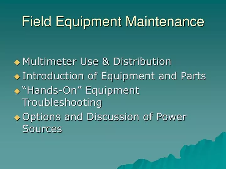
Field Equipment Maintenance. Multimeter Use & Distribution Introduction of Equipment and Parts “Hands-On” Equipment Troubleshooting Options and Discussion of Power Sources. Multimeter. Use to verify power AC/DC Check fuses for continuity DC backup voltage E.R voltage

E N D
Field Equipment Maintenance • Multimeter Use & Distribution • Introduction of Equipment and Parts • “Hands-On” Equipment Troubleshooting • Options and Discussion of Power Sources
Multimeter • Use to verify power AC/DC • Check fuses for continuity • DC backup voltage • E.R voltage • Hybrid battery voltage
Aerochem Metrics wet/dry collector Troubleshooting and Maintenance Appendix C
Pictorial Guide to Parts Part NumberName 1 sensor unit 2 collector frame 3 sensor screws 4 sample bucket holder 5 sensor grid 6 sensor plate
Pictorial Guide to Parts Part NumberName • Motorbox screws • Sampling bucket holder screws • Motorbox unit • Clutch arm unit • Clutch arm machine bolt • Counterweight • Waldes ring • Push rod • Counter weight rod • Lid drive arms • Lid tension springs • 110V AC power cord • Event recorder terminal • Sensor unit socket 33 Silver drive arm
Pictorial Guide to Parts Part Number Name 7 motor box screws 10 clutch arm unit 18 110V AC power cord 19 event recorder terminal 20 sensor unit socket 21 12V DC power lugs 22 12V DC circuit fuse 23 110V AC circuit fuse 24 event recorder circuit fuse
Pictorial Guide to Parts Part NumberName 25 Motorbox stop switches 26 E.R./wet mode heater switch 27 Drive motor switch 28 Clutch tooth 29 Thrust collar set screw 30 Clutch tooth tension plate 31 Switching magnets 32 Clutch tooth tension spring
Symptom Collector lid stays over the dry-side bucket long after precipitation stops, sensor dries slowly (more than 30 minutes for rain), motor not running. (If motor is running, see Clutch Unit - “What Goes Wrong”.) Collector lid oscillates non-stop between buckets, sensor wet or dry. Collector lid stays over wet-side bucket, sensor wet, motor not running. (If motor is running, see Clutch Units - “What GoesWrong”.) See Flow Chart #1, page C-19 #5, page C-23 #6, page C-24 Sensor Problems
Symptom Collector lid stays over dry side bucket, sensor dry, motor not running. (Again, if motor is running, see Clutch Units - “What Goes Wrong”). Sensor plate (6) snow covered or iced up. See Flow Chart #4, page C-22 #3, page C-21 Sensor Problems
Symptom Collector lid stays over the dry-side bucket long after precipitation stops, sensor dries slowly (more than 30 minutes for rain), motor not running. If motor running, see Clutch Unit - Collector lid stays over wet-side bucket, sensor wet, motor not running. If running, see Clutch Unit - Collector lid stays over dry-side bucket, sensor dry, motor not running. If running, see Clutch Unit - Collector lid oscillates non-stop between buckets, sensor wet or dry. See Flow Chart #1, page C-19 #4, page C-24 #4, page C-22 #5, page C-23 Motorbox Problems
Belfort Recording Raingage Troubleshooting and Maintenance Appendix D
Introduction • The Belfort recording raingage records positive increases in precipitation • Event Recorder shows openings/closings of collector
Pictorial Guide to Parts Part NumberName 1 Catch Bucket 2 Zero Adjustment Screw(s) and Setting Bar 3 Limit Screw(s) 5 Precipitation Pen Arm 6 Mechanism Base 7 Pen Tip 8 Pen Shifter 9 Chart Drum With Clip 10 Bucket Platform 13 Clock 11 Top Lever 14 Pen Arm Stud 15 Event Recorder 16 Bucket Support Shaft
Part NumberName 2 Zero adjustment screws and setting bar 3 Limit screws 4 Fine Linkage 6 Mechanism Base 7 Pen Tip 10 Bucket Platform 11 Top Lever 12 Dashpot 15 Event Recorder 16 Bucket Support Shaft Pictorial Guide to Parts
Pictorial Guide to Parts Part NumberName 17 Top Cap 18 Funnel 19 E. R. Solenoid 20 E. R. Pen and Arm 21 E. R. Pivot Point 22 E. R. L-Bracket
Cleaning the Belfort After removing the “can”, compressed air or small paint brush can be used to remove debris. Gumout or other zero residue cleaner should be sprayed at each moving part or joint.
Winterization • Remove evaporation shield • Add Antifreeze • Standard Automotive ethylene glycol • RV propylene gylcol • 2 quarts = ~2.75” • Refresh as necessary
Summerization • Install evaporation shield • Remove Antifreeze • Dispose of Antifreeze properly
Lid seal change • Change annually or if damaged • Best to change on first Tuesday of the month • Clean after installation • Change wet side and dry side buckets
ACM Power Troubleshooting-DC • Power System 1.c. DC ONLY 1.d. DC Solar 1. Overall View 2. Cell/Regulator/Battery diagram 3. External Regulator Check 3.a Blocking Diode Check 3.b. Charge Control Check 1.e. Load Testing Batteries
DC ONLY • ACM requires up to 180 AMPS/week (more in winter to provide ambient heater) • Weekly battery changes needed
DC Solar Overall View + _ + _ External Regulator with blocking diode + _ 12 volt Deep cycle battery system + _ + _ + _ In-line 5A fuse holder and fuse Precipitation Collector
DC Solar Cell/Regulator/Battery diagram At full sun, panels can produce > 22 volts DC • External Regulator • 2 jobs • Keep charge voltage < ~ 16-18V. • If > damage battery. • 2. Keep system from discharging. • Blocking diode lets power go only • 1 way (to battery). I N P U T O U T P U T PANEL e+ + - + - + - - +
External Regulator Check(see Cell/Regulator/Battery diagram) • Blocking Diode Check • 1. Disconnect solar panel wires from external regulator. • Test with VOM for power at regulator INPUT position. • If > ~ 5 V DC; regulator is bad, allowing panel to discharge the battery through regulator. • If < 5 V DC; regulator is O.K. • Charge Control Check • 1. Disconnect solar panel wires from external regulator and measure DC coming from unregulated panel. • If sunny, ~ 18-22 V DC • If cloudy, < 14-16 V DC • 2. Reconnect wires from solar panel to regulator and disconnect OUTPUT side wires from regulator to battery. • Test regulator output, even in full sun output < 16 V DC
Load Testing Batteries • VOM check does not ensure battery is “good”. Battery should be removed from site, hard charged and then load tested by battery shop. • Portable load testers can be purchased for ~ $50.00. • Recommended as standard equipment for DC, DC/solar sites.