Download
1 / 31
310 likes | 428 Views
Caged-Dye Imaging of Flows in Microfabricated Systems. Microfluidics Laboratory, Dept of Mechanical Engineering 2009 G. G. Brown Laboratory, 2350 Hayward Street, Ann Arbor MI 48109 Advisor : Ernest F. Hasselbrink, Jr. Students Taesung Kim (PhD) Sun Min Kim (PhD) Meng Ping Chang (PhD)

E N D
Caged-Dye Imaging of Flows in Microfabricated Systems Microfluidics Laboratory, Dept of Mechanical Engineering 2009 G. G. Brown Laboratory, 2350 Hayward Street, Ann Arbor MI 48109 Advisor: Ernest F. Hasselbrink, Jr. Students Taesung Kim (PhD) Sun Min Kim (PhD) Meng Ping Chang (PhD) Sanghyun Lee (PhD) Donghyuck Kam (MS) Robert Bartz (MS) Anders Brask (visiting PhD, TUDenmark) Rachel Lance (BS) Alumni Jesse Kirchner, MS Sneha Madhavan-Reese, MS Jung Yim Min, visiting PhD student, KAIST Contact info: microflow.engin.umich.edu Lab phone 734-936-0343 Acknowledgments: NSF WIMS Center, DARPA/DSO, NIH/NIDCR, NASA JPL DRDF
Electrokinetic pumping (MP Chang, A. Brask, R. Bartz) • Flux through a tube:
O Capillary/channel R O Mask UV light monomer O O cross-linker Initiator/ solvent O O Mobile UV-lithographed Polymer Monoliths • “Ship-in-a-bottle” approach • Electrokinetic or DP mobilization • ~1 psi required for actuation • Material may be tailored for mechanical strength, charge, porosity, etc. (multi-component monomers & solvents) 50 mm
bypass piston Ultimate Goal – mFluidic Engineering Toolbox • We want analogues of the basic functional units we are used to dealing with in the macroscale world • mvalves, mpipettes, actuators, injectors, regulators, etc… • Example: Check-Valve • Dual-level, dual-side HF etch • Photo-initiation at 355 nm
Multi-Port Diverter (XOR gate) A inlet B inlet
pistons pistons 10 nL Pipette load dispense sample inlet running column
Motivation: Standard dye imaging lacks spatial resolution due to diffusion Fluorescent dye imaging does not provide contrast over short enough length scales to resolve EOF/PDF components, or to reveal flow details over channel-diameter lengthscales ddiff ~ (2Defft)1/2 Viewing Region
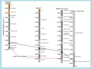
EOF vs. PDF geometric dispersion studies using caged dye EOF can have much lower dispersion … … unless you create sources of geometric dispersion P. H. Paul, unpublished P. H. Paul et al., Anal. Chem. 1998, vol 70 no.13, 2459
UV light (<365nm) CMNCBZ-caged-carboxy-Q-rhodamine dye Uncaged-carboxy-Q-rhodamine dye Caged-Dye Imaging Process of uncaging caged-dye using UV light
Caged Dye Imaging Apparatus • 20mm-thick sheet of 355nm light uncages dye • Array of pulsed blue LED’s (lc=460nm) or inverted fluorescence microscope Hg lamp induces fluorescence of uncaged dye (lc=540nm).
500μm Caged Dye Imaging Example
500μm Caged Dye Imaging Example
500μm 500μm Caged Dye Imaging Example
Practical Caged Dye Notes • Dextran, 5-(and-6)-carboxy-Q-rhodamine, CMNCBZ-caged dye, anionic : 10,000MW, 5mg-155.00$, D34678 (probes.com) • Dextran, DMNB-caged fluorescein, anionic : 10,000MW, 5mg-155.00$, D3310 (probes.com) • Dextran, DMNB-caged fluorescein and biotin, lysine fixable : 70,000MW, 5mg-254.00$, D7147 (probes.com) • Typical preparation: • Buffer solution: pH 8.0+, 5mM+ ionic strength • Concentration: ~1 mg/mL or less • Keeping: T< -20 oC.
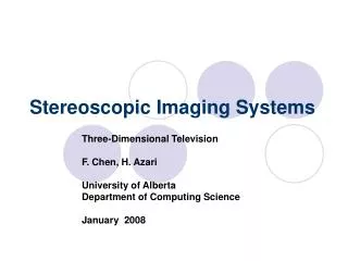
Principle of Particle Imaging Velocimetry t=t0 t=t0+dt • Images of particles at different times are recorded on a camera. • By measuring the particle displacements, the motion of the fluid can be ascertained. • Tracer particles follow the fluid motion. • Tracer particles are distributed homogeneously and properly.
Particle Imaging Procedure Experimental Setup Image Processing Preprocessing Seeding Interrogation & Correlation Fluid Flow Velocity Field Illumination Image capturing Postprocessing
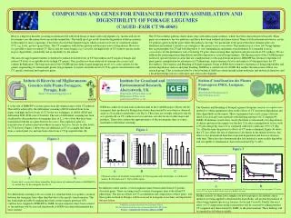
Flow In Flow Out Focal Plane (δz) << Ldepth δz ~ 2.0um in 60x w/ immersion oil δz ~ 8.0um in 40x w/o immersion oil Microscope Objective / CCD Camera (1332X1024 16bit) Particle Imaging Experimental Setup Ldepth Trasparent material (e.g., glass) 1. single frame/multi-exposure 2. multi-frame/single exposure
- = Image Processing - Preprocessing Subtraction of Background Noise The most important image processing that should be done prior to any others. Courtesy of S.H. Lee
Image Processing - Interrogation T=t2 T=t1 • PTV (Particle Tracking Velocimetry) - Tracking each particle movementwith time Velocity • PIV (Particle Image Velocimetry) - The images are divided into small subsections, interrogation areas(~10particles/IA), and then average interrogation movement with time Velocity
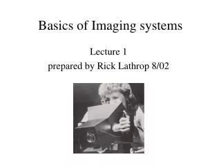
y x Image Processing –Cross/Auto Correlation - multi-frame/single exposure Cross Correlation Displacement = Center to Peak - single frame/multi-exposure Auto Correlation Displacement = Center to either of peaks Directional Ambiguity Fromhttp://www.ph.ed.ac.uk/~ted/thesis/node41.html
Image Processing Result using PIV Sleuth Courtesy of S.H. Lee
Error Sources • Too high particle density Background noise from out-of-focus particles reduce the visibility of in-focus paricles. • Too low particle density Standard cross correlation techniques will fail to provide an adequate signal. • Microchannel Focal plane depth should be carefully considered. • Brownian motion for a single particle < 3% full-scale error.
Practical Particle Imaging Notes • General PIV Overview (http://www.ph.ed.ac.uk/~ted/thesis/node32.html ) • PIV Sleuth (free software and manual download http://ltcf.tam.uiuc.edu/) • Matlab m.file for PIV(http://matlabpiv.sourceforge.net/) • Particle Purchase • Molecular Probes (http://www.probes.com) • Fluo spheres carboxylate-modified microspheres 0.1um Yellow-Green fluorescent ($191.00)
Reference Papers • Adrian RJ (1991) Particle Imaging techniques for experimental fluid mechanics, Ann Rev Fluid Mech 23:261-304. • Prasad AK, Adrian RJ, Landreth CC, Offutt PW (1992) Effect of resolution on the speed and accuracy of particle image velocimetry interrogation, Exp Fluids 13:105-116. • Meinhart CD, Wereley ST, Santiago JG, (1999) PIV measurements of a microchannel flow, Exp Fluids 27:414-419 • Devasenathipathy S, Santiago JG, Wereley ST, Meinhart CD, Takehara K, (2003) Paricle imaging technique for microfabricated fluidic systems, Exp. Fluids 34:504-514