Download
1 / 35
370 likes | 397 Views
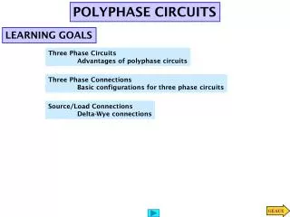
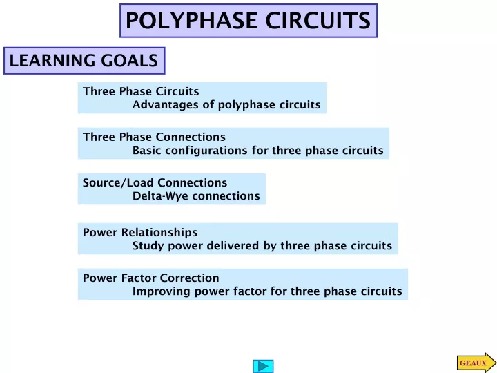
POLYPHASE CIRCUITS. LEARNING GOALS. Three Phase Circuits Advantages of polyphase circuits. Three Phase Connections Basic configurations for three phase circuits. Source/Load Connections Delta-Wye connections. Power Relationships Study power delivered by three phase circuits.

E N D
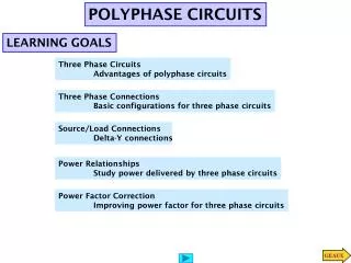
POLYPHASE CIRCUITS LEARNING GOALS Three Phase Circuits Advantages of polyphase circuits Three Phase Connections Basic configurations for three phase circuits Source/Load Connections Delta-Wye connections Power Relationships Study power delivered by three phase circuits Power Factor Correction Improving power factor for three phase circuits
Theorem For a balanced three phase circuit the instantaneous power is constant THREE PHASE CIRCUITS
Proof of Theorem For a balanced three phase circuit the instantaneous power is constant
Positive sequence a-b-c Y-connected loads Delta connected loads THREE-PHASE CONNECTIONS
Line voltages Positive sequence phase voltages SOURCE/LOAD CONNECTIONS BALANCED Y-Y CONNECTION For this balanced circuit it is enough to analyze one phase
Positive sequence a-b-c Positive sequence phase voltages Balanced Y - Y Relationship between phase and line voltages LEARNING EXAMPLE For an abc sequence, balanced Y - Y three phase circuit Determine the phase voltages The phasor diagram could be rotated by any angle
Chosen as reference Abc sequence LEARNING EXAMPLE For an abc sequence, balanced Y - Y three phase circuit Because circuit is balanced data on any one phase is sufficient Determine line currents and load voltages
Relationship between phase and line voltages LEARNING EXTENSION For an abc sequence, balanced Y - Y three phase circuit
Positive sequence a-b-c LEARNING EXTENSION For an abc sequence, balanced Y - Y three phase circuit Determine source phase voltages Currents are not required. Use inverse voltage divider
Convert to an equivalent Y connection Example Relationship between phase and line voltages DELTA CONNECTED SOURCES
Source is Delta connected. Convert to equivalent Y LEARNING EXAMPLE Determine line currents and line voltages at the loads Analyze one phase Determine the other phases using the balance
Source is Delta connected. Convert to equivalent Y Compute the magnitude of the line voltage at the load LEARNING EXTENSION Analyze one phase Only interested in magnitudes!
Positive sequence phase voltages Line-phase current relationship DELTA-CONNECTED LOAD Method 1: Solve directly Method 2: We can also convert the delta connected load into a Y connected one. The same formulas derived for resistive circuits are applicable to impedances
LEARNING EXTENSION Line-phase current relationship
REPLACE IN THE THIRD AND SOLVE FOR R1 SUBTRACT THE FIRST TWO THEN ADD TO THE THIRD TO GET Ra
Alternatively, determine first the line currents and then the delta currents Line-phase current relationship Delta-connected load consists of 10-Ohm resistance in series with 20-mH inductance. Source is Y-connected, abc sequence, 120-V rms, 60Hz. Determine all line and phase currents LEARNING EXAMPLE
- Impedance angle Power factor angle Line-phase current relationship POWER RELATIONSHIPS
- Impedance angle Power factor angle Line-phase current relationship LEARNING EXAMPLE Determine the magnitude of the line currents and the value of load impedance per phase in the delta
Chosen as reference Because circuit is balanced data on any one phase is sufficient Abc sequence LEARNING EXAMPLE For an abc sequence, balanced Y - Y three phase circuit Determine real and reactive power per phase at the load and total real, reactive and complex power at the source
inductive capacitive Determine the line currents and the combined power factor LEARNING EXAMPLE Continued ...
inductive capacitive LEARNING EXAMPLE continued ….
A Y -Y balanced three-phase circuit has a line voltage of 208-Vrms. The total real power absorbed by the load is 12kW at pf=0.8 lagging. Determine the per-phase impedance of the load Impedance angle Power factor angle LEARNING EXTENSION
Determine real, reactive and complex power at both load and source Source is Delta connected. Convert to equivalent Y Analyze one phase LEARNING EXTENSION
A 480-V rms line feeds two balanced 3-phase loads. The loads are rated Load 1: 5kVA at 0.8 pf lagging Load 2: 10kVA at 0.9 pf lagging. LEARNING EXTENSION Determine the magnitude of the line current from the 408-V rms source
POWER FACTOR CORRECTION Similar to single phase case. Use capacitors to increase the power factor Balanced load Low pf lagging Keep clear about total/phase power, line/phase voltages To use capacitors this value should be negative
Determine the current flowing. Convert line voltages to phase voltages Equivalent 1-phase circuit LEARNING EXAMPLE MEASURING POWER FLOW Which circuit is the source and what is the average power supplied? Phase differences determine direction of power flow! System Y is the source
INCREMENTAL COST OF POWER FACTOR CORRECTION LEARNING EXAMPLE Desired: Supplied by capacitors • least expensive at • very expensive as How much capacitance is required to improve the power factor by a fixed amount (say 0.01)
LEARNING EXAMPLE Choices available CAPACITOR SPECIFICATIONS Capacitors for power factor correction are normally specified in VARs Capacitor 1 is not rated at high enough voltage! Capacitor 3 is the best alternative
1. Is the wire suitable? 2. What capacitance would be required to have a composite pf =0.92 lagging Capacitors are to be Y - connected LEARNING BY DESIGN Proposed new store Wire is OK
DESIGN OF A 3-PHASE EMULATOR Magnitude Adjustor Design equations for adjustor Powered by 120V(RMS) – standard wall outlet using a transformer with turns ratio Potentiometers are more restricted. Select LEARNING EXAMPLE
buffer 3-PHASE EMULATOR - CONTINUED • SOLUTION: • Use RC network for -60 deg (lag) • Use inverter for -180 phase shift
USE 10k RESISTORS FOR UNIFORMITY 3-PHASE EMULATOR - CONTINUED
Polyphase 3-PHASE EMULATOR – PROPOSED SOLUTION