Download
1 / 10
120 likes | 275 Views
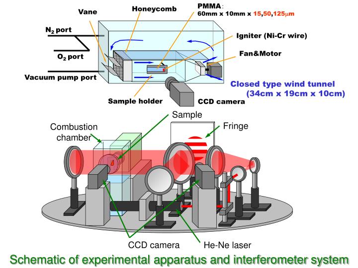
Sample. Fringe. Combustion chamber. PMMA : 60mm x 10mm x 15 , 50 , 125 m m. Honeycomb. Vane. N 2 port. Igniter (Ni-Cr wire). Fan&Motor. O 2 port. Vacuum pump port. Closed type wind tunnel (34cm x 19cm x 10cm). Sample holder. CCD camera. CCD camera. He-Ne laser.

E N D
Sample Fringe Combustion chamber PMMA: 60mm x 10mm x 15,50,125mm Honeycomb Vane N2 port Igniter (Ni-Cr wire) Fan&Motor O2 port Vacuum pump port Closed type wind tunnel (34cm x 19cm x 10cm) Sample holder CCD camera CCD camera He-Ne laser Schematic of experimental apparatus and interferometer system
Solenoid coil Opposed Flow Ni-Cr wire Sample holder turnable Spring Solenoid coil Sample Base mG for 4.5 sec Sample holder (sample size: 6cm x 1cm) Fan & Motor Video camera Ignite the sample 1.6 sec before mG. Remove the igniter 0.3sec before mG. Details of sample holder and typical sequence of drop experiments
Move to the drop shaft 1 2 Close the capsule 4 3 Assemble Ready to drop MGLAB 100m drop Attach the transceiver
* * t: 15mm t: 50mm t: 125mm The minimal value appears at Vg~-6cm/s The minimal value appears at Vg~-3cm/s The minimal value appears at Vg~0cm/s The hydrodynamic constant, ch,FP, was determined by matching the computed and predicted spread rates. (Eq. 7) (26th International Symposium on Combustion) Flame spread rate in microgravity with varying t,Vg and O2 level
* 15mm 50mm 125mm 15mm * 50mm 125mm 15mm 50mm 125mm O2: 21% O2: 50% O2: 30% Dimensionless radiation parameter, R Dimensionless spread rate vs. dimensionless relative flow velocity
Lgy Lgx micro-gravity Lgx~Lgy~1.7cm Lgy Lgx normal gravity Lgx~Lgy~0.27cm =1cm =1cm Micro-gravity Quiescent condition Thickness: 50mm O2 level: 50% Vf+Veqv~10mm/sec Buoyant flow Normal-gravity Quiescent condition Thickness: 50mm O2 level: 50% Vf+Veqv~65mm/sec Sizes of the preheat zone in microgravity and in normal gravity
Quiescent condition Thickness: 125mm O2 level: 30% Quiescent condition Thickness: 50mm O2 level: 50% R=0.95 R=0.14 Photo Sketch Photo Sketch The fringes move the opposed direction to that of flame spread, which implies that temperature is decreasing in time, thus unsteady. The fringes move to the same direction that the flame moves, and it implies that the steady temperature field is achieved. Histories of temperature field near the flame front
Data from 4.5 s MGLAB Drop Tower Quiescent Environment, Steady Spread Opposed flow: Vg=0 Thickness: 50 mm O2 level: 50% Pressure 1 atm Fuel: Thin PMMA Interferometer Video, Side View CCD Video, Top View
Data from 4.5 s MGLAB Drop Tower Quiescent Environment - Extinction Opposed flow: Vg=0 Thickness: 125 mm O2 level: 30% Pressure 1 atm Fuel: Thin PMMA Interferometer Video, Side View CCD Video, Top View
Data from 4.5 s MGLAB Drop Tower Flow Reversal, 50 mm thick, 30% O2, 1 atm Vg=30 mm/s Vg=0 Vg=-30 mm/s