Download
1 / 36
360 likes | 477 Views
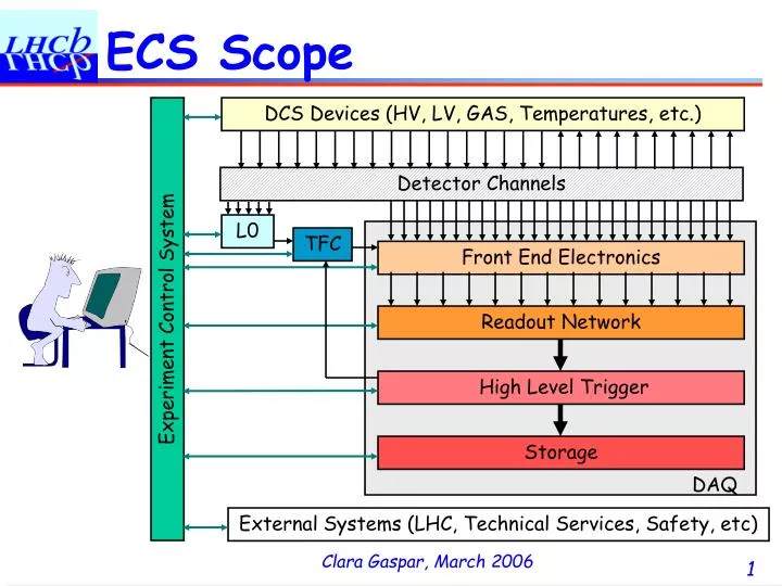
ECS Scope. DCS Devices (HV, LV, GAS, Temperatures, etc.). Detector Channels. L0. TFC. Front End Electronics. Experiment Control System. Readout Network. High Level Trigger. Storage. DAQ. External Systems (LHC, Technical Services, Safety, etc). ECS Generic Architecture. ECS. T.S.

E N D
ECS Scope DCS Devices (HV, LV, GAS, Temperatures, etc.) Detector Channels L0 TFC Front End Electronics Experiment Control System Readout Network High Level Trigger Storage DAQ External Systems (LHC, Technical Services, Safety, etc)
ECS Generic Architecture ECS T.S. LHC DAQ DSS DCS ... ... Abstract levels GAS DetDcs1 DetDcsN DetDaq1 Status & Alarms Commands SubSys1 SubSys2 SubSysN Dev1 Dev2 Dev3 DevN To Devices (HW or SW)
What do we provide? • JCOP + LHCb Online provide: • Not complete applications, but: • A Framework, i.e. a set of tools to help sub-systems create their control systems: • Complete, configurable components (ex. CAEN HV) • Tools for defining User Components: • Electronics boards (SPECS/ CC-PC) • Specific equipment/software tasks (DIM protocol) • Other Tools, for example: • FSM for Building Hierarchies • Configuration DB • Archiving, Alarm handling, etc.
We also provide: • Integration of Infrastructure Services: • Power Distribution and Rack/Crate Control • Cooling and Ventilation Control • Magnet Control (Monitoring) • Gas Control • Detector Safety System • And interface to: • LHC machine • Access Control System • CERN Safety System • Sub-detectors can use these components: • For defining logic rules (using their states) • For high-level operation (when applicable) • Switch ON, Switch Off, Set parameters
Experimental Equipment And also Database Tools • Interfaces to the three Logical Databases in the Online System Conf. DB ... ... PVSS PVSS PVSS PVSS PVSS Arch. PVSS PVSS PVSS PVSS ... ... . . Cond. To Offline To Offline DB
Online Database Contents • Configuration DB contains: • All data needed to configure the HW (or SW) for the various running modes • Ex.: HV V0 Settings, Pedestal settings, trigger settings, etc. • PVSS Archive contains: • All monitoring data read from HW for monitoring and debugging of the Online System • Ex.: HV Vmon Readings, temperatures, pedestal readings, etc. • Conditions DB contains: • A subset of the monitoring data read from HW if it is needed for Event processing (prob. packaged differently) • Ex.: HV Vmon Readings if changed by more than n Volts • Some configuration data once it has been used • Ex.: Trigger settings used by a particular run
The Configuration DB • The Configuration DB will contain: • All "static" information about the devices • Connectivity, addresses, etc. (also inventory and history) • Developed within LHCb (supports queries) • All "dynamic" data needed by the devices (for different running modes and different versions): • Settings (voltages, alarm limits, etc.), Calibration constants, Pedestals, FPGA code (probably a pointer to it), etc. • The settings for a particular running mode are called a “Recipe” (partial recipes available) • The JCOP FW component implements a cache: • Can be used without Oracle for tests • Can pre-load several recipes before “Start of Run”
What needs to be done: • Start bottom up • Integrate each device into PVSS • Define configuration recipes • for the various running modes • Build a hierarchy for each sub-system • According to the guidelines • Integrate the devices in the hierarchy
Device Integration • Device Types • HV & LV channels • CAEN, ISEG, WIENNER -> JCOP Framework • Analog inputs • ELMB -> JCOP Framework • Electronics boards • SPECS & CC-PC -> Tools to describe boards • TELL1 -> FW component (for common part) • Other Components • HW or SW -> FwDIM component • Needs: PVSS, Framework, DIM,…
Datapoint Concept • DP type -> DP Configs
Graphical Objects • Reference Panels • Can be “inherited” dynamically • “$parameters” get replaced by instance value
Building User Interfaces • Static Part -> Drag & Drop • Dynamic part -> Control Scripts ("C" like) • A few usefull calls for accessing DPs: • dpGet (string dpName, <data_type> value) • dpSet (string dpName, <data_type> value) • dpConnect (string callback, string dpName) • A few usefull calls for accessing Widgets: • getValue (string widgetName, string widgetProperty, <widget dependent data>) • setValue (string widgetName, string widgetProperty, <widget dependent data>)
PVSS Features • Open Architecture • We can write our own managers • It can be interfaced to anything (FSM, DIM) • Highly Distributed • 130 Systems (PCs) tested • No major problem found • Standard Interface • All data of all sub-systems defined as DataPoints!
Electronics Integration • Electronics Boards: • Can use the CCPC/SPECS FW Tools for tests, but accessing the “chips” is not enough • Boards have to be modeled in PVSS according to guidelines (ex. registers have to correspond to datapoints) in order to: • Provide access to the Conf. DB • Select a device/group of devices and say:Save as “Physics” recipe. • Be able to archive the data • Be able to send the data to the Cond. DB • Integrate into the FSM, Generate alarms, etc.
Electronics Integration • We provide a tool for modeling boards and their components (FWcomponent: FwHw) • Declaring boards (access via SPECS or CC-PC)Containing: • Groups of Chips (recursive) Containing: • Chips (TTCrx, Beetle, etc.)Containing: • Registers (access via I2C/JTAG/Parallel Bus) • Contacts: • Ricardo Fernandes: SPECS • Stefan Koestner: CC-PC
Electronics guidelines • FwHw: Some Guidelines • If a “chip” has many registers • If they can be written in one single operation • Declare them as 1 register of size N • This will optimize configuration time • Some (a few) can also be declared separately • If they are often accessed individually • After using FwHw to define the boards: • Design a user interface to operate each board type • The library fwSpecs or fwCcpc will give you access to the data to be visualized or sent to the board ex.: fwSpecs_read(“board1.ttcrx1.reg2”,…)
Control Hierarchy • Building a Control Hierarchy • And integrating Devices • Needs: FwFSM, LHCb guidelines ECS T.S. LHC DAQ DSS DCS ... ... GAS DetDcs1 DetDcsN DetDaq1 SubSys1 SubSys2 SubSysN Dev1 Dev2 Dev3 DevN
Control Units • Each node is able to: • Summarize information (for the above levels) • “Expand” actions (to the lower levels) • Implement specific behaviour& Take local decisions • Sequence & Automate operations • Recover errors • Include/Exclude children (i.e. partitioning) • Excluded nodes can run is stand-alone • User Interfacing • Present information and receive commands DCS Tracker Muon HV Temp HV GAS
Device Units • Device Units • Provide the interface to real devices:(Electronics Boards, HV channels, trigger algorithms, etc.) • Can be enabled/disabled • In order to integrate a device within FSM • Deduce a STATE from device readings (in DPs) • Implement COMMANDS as device settings • Commands can apply the recipes previously defined DevN
The Control Framework • The FwFSM Component is based on: • PVSS for: • Device Description (Run-time Database) • Device Access (OPC, Profibus, drivers) • Alarm Handling (Generation, Filtering, Masking, etc) • Archiving, Logging, Scripting, Trending • User Interface Builder • Alarm Display, Access Control, etc. • SMI++ providing: • Abstract behavior modeling (Finite State Machines) • Automation & Error Recovery (Rule based system) Device Units Control Units
SMI++ • Method • Classes and Objects • Allow the decomposition of a complex system into smaller manageable entities • Finite State Machines • Allow the modeling of the behavior of each entity and of the interaction between entities in terms of STATES and ACTIONS • Rule-based reasoning • Allow Automation and Error Recovery
SMI++ • Method (Cont.) • SMI++ Objects can be: • Abstract (e.g. a Run or the DCS) • Concrete (e.g. a power supply or a temp. sensor) • Concrete objects are implemented externally either in "C", in C++, or in PVSS (ctrl scripts) • Logically related objects can be grouped inside "SMI domains" representing a given sub-system (Framework: Control Unit)
SMI Domain Obj SMI Domain Obj Obj Obj Obj Obj Obj Obj Proxy Proxy Proxy SMI++ Run-time Environment • Device Level: Proxies • drive the hardware: • deduceState • handleCommands • C, C++, PVSS ctrl scripts • Abstract Levels: Domains • Implement the logical model • Dedicated language - SML • A C++ engine: smiSM • User Interfaces • For User Interaction • All Tools available on: • Windows, Unix (Linux) • All communications are transparent and dynamically (re)established Hardware Devices
SMI++ • SMI++ - The Language • SML –State Management Language • Finite State Logic • Objects are described as FSMstheir main attribute is a STATE • Parallelism • Actions can be sent in parallel to several objects. Tests on the state of objects can block if the objects are still “transiting” • Asynchronous Rules • Actions can be triggered by logical conditions on the state of other objects
SML – The language • Devices: • Sub System: • Objects can be dynamically included/excluded in a Set
SML example (automation) • External Device: • Sub System:
PVSS/SMI++ Integration • Graphical Configurationof SMI++ Using PVSS
Building Hierarchies • Hierarchy of CUs • Distributed over several machines • "&" means reference to a CU in another system • Editor Mode: • Add / Remove / Change Settings • Navigator Mode • Start / Stop / View
Control Unit Run-Time • Dynamically generated operation panels(Uniform look and feel) • Configurable User Panels
Features of PVSS/SMI++ • Task Separation: • SMI Proxies/PVSS Scripts execute only basic actions – No intelligence • SMI Objects implement the logic behaviour • Advantages: • Change the HW -> change only PVSS • Change logic behavioursequencing and dependency of actions, etc -> change only SMI rules
Sub-detector FSM Guidelines • Started defining naming conventions. • Defined standard “domains” per sub-detector: • DCS • DCS Infrastructure (Cooling, Gas, Temperatures, pressures, etc) that is normally stable throughout a running period • HV • High Voltages or in general components that depend on the status of the LHC machine (fill related) • DAQ • All Electronics and components necessary to take data (run related) • DAQI • Infrastructure necessary for the DAQ to work (computers, networks, electrical power, etc.) in general also stable throughout a running period. • And standard states & transitions per domain. • Doc available in EDMS: • https://edms.cern.ch/document/655828/1
FSM Guidelines • State Diagram for Trigger and DAQ Domains: • Possible intermediate “CONFIGURING” and “STARTING” states if operations slow…
ECS Hierarchy Infrast. DCS HV DAQI DAQ L0 TFC HLT LHC SubFarm1 SubFarmN MUONDCS MUONHV MUONDAQI MUONDAQ VELODCS VELOHV VELODAQI VELODAQ VELODAQ_1 VELODAQ_2 VELODCS_1 VELODCS_2 VELODev1 VELODev1 VELODev1 VELODevN
ECS Hierarchy & Conf. DB 1 Infrast. DCS HV DAQI DAQ L0 TFC HLT LHC 1 MUONDCS MUONHV MUONDAQI MUONDAQ Conf. VELODCS VELOHV VELODAQI VELODAQ 2 DB 1 VELODAQ_1 VELODAQ_2 VELODCS_1 VELODCS_2 VELODev1 3 VELODev1 Configure/mode=“PHYSICS” (Get “PHYSICS” Settings) Apply Settings 1 VELODev1 VELODevN 2 3
ECS VELO Hierarchy & Partitioning Infrast. DCS HV DAQI DAQ L0 TFC HLT LHC MUONDCS MUONHV MUONDAQI MUONDAQ VELODCS VELOHV VELODAQI VELODAQ VELODAQ_1 VELODAQ_2 VELODCS_1 VELODCS_2