Download
1 / 19
200 likes | 571 Views
Bialkali Photocathode Development . Ossy Siegmund, Experimental Astrophysics Group, Space Sciences Laboratory, U. California at Berkeley. Some LAPD Photocathode Milestones.

E N D
Bialkali Photocathode Development Ossy Siegmund, Experimental Astrophysics Group, Space Sciences Laboratory, U. California at Berkeley
Some LAPD Photocathode Milestones • Systematic characterization of Photo-electron Emission (PE) properties of materials for photocathode development. • Demonstration of an operational 8”-square photo-cathode with a viable path to QE ≥ 15% for wavelengths between 300 and 450 nm. Associated Milestones - Dependencies:- • Demonstration of the window-to-body seal solution. • Design and costing of the vacuum-transfer/assembly facility for the 8”-square MCP module.
Cathode Bandpass and Windows Acceptable cutoff range Nominal Cherenkov emissionspectrum compared with bialkali Typical window transmission curves
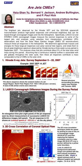
Bi-Alkali Cathode Characteristics Lyashenko, Chicago 7/09 2*106Ohm/square 6*109Ohm/square Cathode Noise vsTempexpect 10,000 to 40,000events/sec for 8” tube bialkali! QE and resistivity for various bialkaliswe will use K2CsSb & Na2KSb
Bialkali Photocathode Configuration • Numerous processes affect the QE Bialkali is a few 100Å thick,and is nominallya deposition as a semitransparentlayer on the window, with a proximity gapto the first MCP.
Bialkali Photocathode QE Schyns, Clermont 2010 High efficiency Bialkali cathodes at Photonis. Clear room for improvement over standard bialkalis. BUT-Need to establish enhancement techniques andverify PMT - to – transfer cathode ispossible. Examples of SSL bialkali photocathode depositions with different wavelength optimizations (on fiber optics). PeakQEs 15% to 20% using Na2KSb.
B33 General Parameters The cathode substrate, window or window coating, affects the photocathode performance. Quartz, fiber optics, 7056 glass are common. Borofloat B33 Borosilicate is not, and also has Tin diffused into one side from the float process, so we are testing this. B33 Composition Refractive index @400nm B33 1.47 Air ~1.0 Water ~1.32 Standard AR coating is bad for LAPD - most likely don’t need AR coating for water/B33 interface
Compatibility and Transmittance of Windows ITO and MgO layers ~ 5nm Thermal 3.25 x 10⁻⁶K Samples coated by Joe Libera, measured by Lisa Pawlowicz B33 Transmittance is typical for borosilicate glasses
ALD ITO/MgO Layer Properties for Windows 1.22” samples Quartz Quartz + ITO 4.5nm Quartz +ITO + MgO 5nm 1.22” samples deconvloved ITO 4.5nm ITO + MgO 5nm Red Blue Black Black Blue Samples coated by Joe Libera, measured by Lisa Pawlowicz Our resistancemeasurementsgive about 104 to 105 Ohms/sq, So very muchcomparable to CERN. Braem, NIMA 2003
Bialkali Cathode Process Program • Small window cathode development, 1.22” samples • Process samples to optimize QE and bandpass • Na2KSb, K2CsSb cathodes • Use several substrate materials, SiO2, verify B33 • Test MgO/ITO/conductor underlayer for cathodes • Large size window cathode study, 8” windows. • Study source alkali design for large cathodes • Develop techniques to make larger area uniform QE • Optimize cathode QE levels • Test metal/ITO conductor underlayer for cathodes • Test metalization and sealing techniques
Tube Lab, 1.2” sample test/process station. • Small tank used to process alkali cathodes (33mm) and tubes of small area. Can take 4-8 samples/run. 3 runs done. • Small sample test runs • Substrate material tests 12
1.22” Cathode Test Samples Old window holders New window holders and mask We have cut up one B33 window to make 30ea 1.22”test samples, alsohave 18ea fused silica as control samples. Inconelannular electrodes were evaporated just as they would be for In seals
Initial Bialkali Trials on 1.2” Sample Substrates • Trying to set up process parameters for comparative tests and optimizations. • Used quartz, B33 and B270 sequential depositions in one pumpdown. • Short process / thin cathode • ended up too blue / low QE. • Had problems with K channels that precluded optimal process, mostly onlater depositions. Process order • Plan for next run • -retool window holders • shoot all substrates in one go at same time • add extra cycles to push peak redder-higher QE Initial cathode trials,
1.22” Substrate Sample test Bialkali Cathodes. • Small sample test runs, 1.22” • Substrate material tests • Fused silica and B33 • ITO and MgO 5nm ALD layers Setup for 3rd run in small tank used to process Bialkali cathodes (1.22”). Can now deposit 4 simultaneous samples/1 cathode shoot. 15
Initial Bialkali Trials on 1.2” Sample Substrates Setting up process parameters for comparative tests and optimizations, 3rd run. Used quartz, B33 + coatings in simultaneous depositions in one pumpdown. Short process / thin cathode, -ended up too blue / low QE. Shows that B33+ITO is good! • Plan for next run • Add extra cycles to push peak redder-higher QE
Cathode/Substrate Progress • Wet cleaning of ITO / MgO ALD coatings is OK - once • Oxygen plasma cleaning of ITO / MgO is NOT OK • Proper pre cleaning of window substrates essential and includes precautions for handling, because initial samples were contaminated and had dust particles • ITO 4.5nm has UV transmission and conductivity as predicted • MgO 5nm UV transmission is good, but QE is not much different than bare quartz • No problems with inconel evaporated borders good adhesion/conduction • Next test run, 8 samples, mostly B33 to test the K2CsSb cathode fabrication • Then do B33 + ITO K2CsSb
Window Seal Development and Cathode Test “Diodes” Now ready to metalize 8.7”window and produce an Indium seal on a frame to test leak tightness of the seal. 3” ceramic body with strip anode, and metal frame with Indium seal 3” window test article on metal frame with Indium seal
8” Tube and Cathode Process Tank System • Large window cathode development, 8.66” square • Fully implement alkali source for large cathode areas • Commission 8” cathode/window seal process tank • Develop wet cleaning and plasma cleaning processes • Commission large full tube process tank (Nov) • Establish metalization tests • Test metal/ITO conductor underlayer for 8” cathodes • Develop techniques to make 8” area uniform QE • Optimize cathode QE levels • Trial seals on 8.66” “frames” • Then • Make LAPD 8” tubes