Download
1 / 54
540 likes | 553 Views
Memory and Advanced Digital Circuits. 1. Latch Circuit Using Cross coupled inverters. Figure 11.1 (a) Basic latch. (b) The latch with the feedback loop opened. (c) Determining the operating point(s) of the latch. SR latch Set – Reset using NOR gates. Reset. Set.

E N D
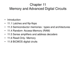
Memory and Advanced Digital Circuits 1
Latch Circuit Using Cross coupled inverters Figure 11.1 (a) Basic latch. (b) The latch with the feedback loop opened. (c) Determining the operating point(s) of the latch.
SR latch Set – Reset using NOR gates Reset Set Figure 11.2 (a) The set/reset (SR) flip-flop and (b) its truth table.
CMOS - Clocked SR Latch Clock f Clock f Reset Set Figure 11.3 CMOS implementation of a clocked SR flip-flop. The clock signal is denoted by f.
Clocked SR Latch - analysis Path used for Simplified Circuit Analysis clock Pull Q! node to Gnd To flip latch to Hi Set Figure 11.4 The relevant portion of the flip-flop circuit of Fig. 11.3 for determining the minimum W/L ratios of Q5 and Q6 needed to ensure that the flip-flop will switch.
Simpler CMOS Clocked SR Latch clock clock Set reset S – R inputs sampled by clock Figure 11.5 A simpler CMOS implementation of the clocked SR flip-flop. This circuit is popular as the basic cell in the design of static random-access memory (SRAM) chips.
D latch Clocked two phase – non-overlapping clocks ? When is output Q valid ? Figure 11.7 A simple implementation of the D flip-flop. The circuit in (a) utilizes the two-phase nonoverlapping clock whose waveforms are shown in (b).
Master Slave D flip flop DFF implementation When is output Q valid ? Edge triggered Figure 11.8 (a) A master–slave D flip-flop. The switches can be, and usually are, implemented with CMOS transmission gates. (b) Waveforms of the two-phase nonoverlapping clock required.
. . . . . . . . . . . . Clocking Methodology Setup – Hold time ? Clk Setup Hold Setup Hold Don’t Care • All storage elements are clocked by the same clock edge • Cycle Time = CLK-to-Q + Longest Delay Path + Setup + Clock Skew • (CLK-to-Q + Shortest Delay Path - Clock Skew) > Hold Time • Setup time: minimum time data signal held steady before clock edge so data reliably sampled. • Hold time:minimum time data signal held steady after the clock edge so data reliably sampled
Monostable Circuit a.k.a. one shot – Multivibrator Creates a single pulse – width = T from a trigger pulse Figure 11.10 A monostable circuit using CMOS NOR gates. Signal source vI supplies positive trigger pulses.
Monostable timing diagram - Analysis G1 output input pulse G2 :Output pulse Figure 11.13 Timing diagram for the monostable circuit in Fig. 11.10.
Multivibrator Circuit = Oscillator As C charges up (eg VO2= VDD; Vt1 decays until G2 trip and goes high Figure 11.15 (a) A simple astablemultivibrator circuit using CMOS gates. (b) Waveforms for the astable circuit in (a). The diodes at the gate input are assumed to be ideal and thus to limit the voltage vI1 to 0 and VDD.
Ring Oscillator A better Oscillator 3 – 5 inverters In cascade Frequency is function of inverter prop delay Figure 11.16 (a) A ring oscillator formed by connecting three inverters in cascade. (Normally at least five inverters are used.) (b) The resulting waveform. Observe that the circuit oscillates with frequency 1/6tP.
Performance of Main Memory: Latency: Cache Miss Penalty Access Time: time between request and word arrives Cycle Time: time between requests Bandwidth: I/O & Large Block Miss Penalty (L2) Main Memory : DRAM: Dynamic Random Access Memory Dynamic: must be refreshed periodically (8 ms, 1% time) Addresses divided into 2 halves (Memory as a 2D matrix): RASor Row Address Strobe CAS or Column Address Strobe Cache :: SRAM: Static Random Access Memory No refresh (6 transistors/bit vs. 1 transistorSize: DRAM/SRAM 4-8, Cost/Cycle time: SRAM/DRAM 8-16 Main Memory Background
Core Memory stored data as magnetization in iron rings Iron “cores” woven into a 2-dimensional mesh of wires Magnetic Core Memories (50s & 60s) IBM 405 Alphabetical Accounting Machine. First magnetic core memory
Semiconductor memory competitive in early 1970s Intel formed to exploit market for semiconductor memory First commercial DRAM Intel 1103 1Kbit of storage on single chip charge on a capacitor used to hold value Semiconductor memory quickly replaced core in 1970s September 2007 , 1GB DRAM < $30 Individuals can easily afford to fill a 32-bit address space with DRAM (4GB) Semiconductor Memory, DRAM
IC memory classification Non-volatile memories Keep data without power supply Volatile memories Lose data when power down SRAM DRAM ROM PROM EPROM EEPROM FLASH EEPROM
SRAM Organization square array • Array 2M rows ´ 2N columns • can be organized as 1, 4, 8 or 16-bit wide • 64M-bit 64M x 1 • 226 bit address • Cells square array • design / layout efficiency Figure 11.17 A 2M+N-bit memory chip organized as an array of 2M rows ´ 2N columns.
1Mb SRAM organization • 1M-bit 1024 rows, 1024 columns • Each cell connected to • a row line (word line) AND • A column line (bit line) • Cell selected by activating word & bit lines • Row & column decoders used • Sense amps. Detect low bit line voltages Figure 11.17 A 2M+N-bit memory chip organized as an array of 2M rows ´ 2N columns.
SRAM Cell Stores one bit Word Line Bit Line Bit Line! Cell looks like ??? Figure 11.18 A CMOS SRAM memory cell.
SRAM Cell Circuit analysis – READ cell contains “1” 1 _ B 0 Q1 ON Figure 11.19 Relevant parts of the SRAM cell circuit during a read operation when the cell is storing a logic 1. Note that initially vQ = VDD and vQ = 0. Also note that the B and B lines are usually precharged to a voltage of about VDD/2. However, in Example 11.2, it is assumed for simplicity that the precharge voltage is VDD.
SRAM Cell Circuit analysis – WRITE “0” operation Figure 11.20 Relevant parts of the SRAM circuit during a write operation. Initially, the SRAM has a stored 1 and a 0 is being written. These equivalent circuits apply before switching takes place. (a) The circuit is pulling node Q up toward VDD/2. (b) The circuit is pulling node Q down toward VDD/2.
SRAM organization • Sense amps. Detect bit line voltages Figure 11.17 A 2M+N-bit memory chip organized as an array of 2M rows ´ 2N columns.
SRAM Sense Amps detect “sense” bit line voltage small voltage swing for speed Amplified by sense amp Figure 11.23 A differential sense amplifier connected to the bit lines of a particular column. This arrangement can be used directly for SRAMs (which utilize both the B and B lines). DRAMs can be turned into differential circuits by using the “dummy cell” arrangement shown in Fig. 11.25.
SRAM Cell Bit line voltage sensing waveforms Small voltage swings Figure 11.24 Waveforms of vB before and after the activation of the sense amplifier. In a read-1 operation, the sense amplifier causes the initial small increment DV(1) to grow exponentially to VDD. In a read-0 operation, the negative DV(0) grows to 0. Complementary signal waveforms develop on the B line.
SRAM Row decode distributed NOR Dynamic precharge 0 0 0 0 0 1 Vdd 0 1 0 0 1 1 1 1 1 Figure 11.26 A NOR address decoder in array form. One out of eight lines (row lines) is selected using a 3-bit address. _ _ _ A2 A2 A1 A1 A0 A0
SRAM Column decode Figure 11.27 A column decoder realized by a combination of a NOR decoder and a pass-transistor multiplexer.
Register File Cell2 Read port1 & 1 write port Read port 0 Read port 1 Write port Write “1” Write “0”
DRAM latch (static) replaced by cell capacitor Capacitive cell must be periodically recharged To retain value stored in cell Figure 11.21 The one-transistor dynamic RAM cell.
1-T DRAM Cell word TiN top electrode (VREF) access transistor Ta2O5 dielectric VREF bit Storage capacitor (FET gate, trench, stack) W bottom electrode poly word line access transistor One Transistor DRAM - FYI
DRAM Architecture bit lines word lines Col. 1 Col.2M Row 1 N Row Address Decoder Row 2N Memory cell(one bit) M N+M Column Decoder & Sense Amplifiers D Data • Bits stored in 2-dimensional arrays on chip • DRAM chips have 4 or more logical banks on each chip • each logical bank physically implemented as smaller arrays
Write: 1. Drive bit line 2. Select row Read: 1. Precharge bit line to Vdd/2 2. Select row 3. Cell and bit line share charges Very small voltage changes on the bit line 4. Sense (fancy sense amp) Can detect changes of ~1 million electrons 5. Write: restore the value Refresh dummy read to every cell. – on a row basis DRAM 1-Transistor Memory Cell row select bit
Three steps to read/write Row access (RAS) decode row address, large number bits / row Bit lines share charge with storage cell Small voltage detected by sense amplifiers - latch whole row of bits sense amplifiers drive bit lines full rail to recharge storage cells Column access (CAS) decode column address to select small number of sense amplifier latches (4, 8, 16, or 32 bits depending on DRAM package) read, send latched bits out to pins Writechange sense amplifier latches, storage cells charged to required value can perform multiple column accesses on same row without another row access (burst mode) Precharge charges bit lines to known value, required before next row access DRAM standards (DDR, DDR2, DDR4, GDDR6, RDRAM) DRAM Operation Read & Write
DRAM access: assertion of RAS_L Followed by CAS RAS_L CAS_L WE_L OE_L A 256K x 8 DRAM D 9 8 RAS_L DRAM Read Timing DRAM Read Cycle Time CAS_L A Row Address Col Address Junk Row Address Col Address Junk WE_L OE_L D High Z Junk Data Out High Z Data Out Read Access Time Output Enable Delay Late Read Cycle: OE_L asserted after CAS_L Early Read Cycle: OE_L asserted before CAS_L
Micron 128M-bit dram (using 2Meg16bit4bank ver) Row (12 bits), bank (2 bits), column (9 bits) Precharge CAS x RAS Burst READ CAS Latency SDRAM timing (Single Data Rate)
[ Micron, 256Mb DDR2 SDRAM datasheet ] Double-Data Rate (DDR2) DRAM 200MHz Row Column Precharge Row’ Data 400Mb/s Data Rate
DRAM has very low voltage swings Differential sensing used FYI Figure 11.25 An arrangement for obtaining differential operation from the single-ended DRAM cell. Note the dummy cells at the far right and far left.
Non-volatile memory Floating gate memories
Programmed by presence / absence of transistor ROM Cell Read only memory Figure 11.29 A simple MOS ROM organized as 8 words ´ 4 bits. Only one word line active at a time
NMOS transistor review Source (S), Drain (D), Gate (G) L channel length, W width of transistor NMOS transistor cross-section
EPROM Cell Additional floating gate Stores “1” / “0” NMOS Figure 11.30 (a) Cross section and (b) circuit symbol of the floating-gate transistor used as an EPROM cell.
MOS transistor: 1 fixedVT Flash memory cell: VT can be changed by program/erase Id Vgs “programming” a floating gate cellchanges VT MOS transistor Floating gate transistor Id programming erasing Vgs VT
Why Flash Memory? • read/written – doesn’t need POWER for data retention. • fast. • durable up to alimit
Applications many, many, more!
Device Structure • Similar to MOSFET • Added Floating Gate (FG) between Control Gate (CG) and inversion layer • FG surrounded by insulators • FG traps electrons (~50 years) • Charged FG disrupts / affects inversion layer • Current flows from the drain to source via inversion layer
Write Function – Logic 0 • Electrons injected into the FG via hot-electron injection • Vt is modified, changing current flow (less) • Reduced current flow in inversion layer logic 0
Effect of “programming”floating gate Figure 11.31 Illustrating the shift in the iD–vGS characteristic of a floating-gate transistor as a result of programming.
Hot electron injection or tunneling results in device deterioration Electrons get trapped in oxide layer Trapped electrons in oxide disrupt Vt Flash Memory can “wear out” Between 1,000 10,000 and up to 100,000 write cycles Lifespan