Download
1 / 18
270 likes | 466 Views
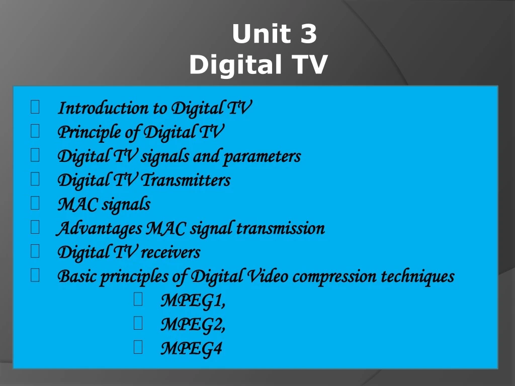
Unit 3 Digital TV Introduction to Digital TV Principle of Digital TV Digital TV signals and parameters Digital TV Transmitters MAC signals Advantages MAC signal transmission Digital TV receivers Basic principles of Digital Video compression techniques MPEG1, MPEG2,

E N D
Unit 3 • Digital TV • Introduction to Digital TV • Principle of Digital TV • Digital TV signals and parameters • Digital TV Transmitters • MAC signals • Advantages MAC signal transmission • Digital TV receivers • Basic principles of Digital Video compression techniques • MPEG1, • MPEG2, • MPEG4
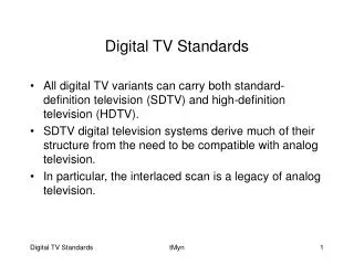
Digital Television? The television system in which analog audio & video signals are converted Into digital binary pulses for transmission and After detection at the receiver are reconverted into analog signals for being Reproduced as original sound & picture is called “Digital Television”
The video signal obtained by converting variation • of the Intensity of light & colour in picture into an • electrical signal,is an analog signal. • For digital,it must be converted into digital pulses • using Analog to digital convertor (ADC) • For display again it must be converted into analog • with Digital to analog convertor (DAC)
Analog signal output of camera & matrix consist • of Luminance (Y) & Colour difference signal U & V. • The composite video signal is sampled at 10 million • samples per second to cover video bandwidth of • 5 Mhz. • Y , U & V signals are quantized to give three streams • of bits / pulses at the o/p of ADC. Signal is sampled • & quantized at ADC. • They are then stored in field store / memory at 50hz • field rate. • For display on screen bits are received at a rate of • 100 hz & converted into digital to analog form by • DAC.
There are 256 inputs through 256 comparators. • Each comparators has two inputs. • One input is connected to tapped voltage & other to • video input. • Output of each comparator is either 0 or 1 • depending upon of matching of video signal • Hence there are 256 input to the encoder. • Encoder gives 8 output which are latched to get a • word of 8 bits.
The video output of white is adjusted to 2 v peak to • peak. • Each resistors drop (2/256) = 7.8 Mv,hence each step • is of 7.8mV. • White signal activates all 256 comparators, while • black Signal operates only 1st comparator. • Thus there are 256 o/p,one o/p at each comparators, • representing each shade. • Thus the system is capable of producing 256 shades.
When clock pulse arrives, 256 o/p are converted into • 8 bit byte by 256 to 8 binary encoder. • These bytes go to latched buffer. • The clock frequency is 13.5 Mhz for normal • broadcast quality to 30 Mhz for HDTV