Download
1 / 69
700 likes | 867 Views
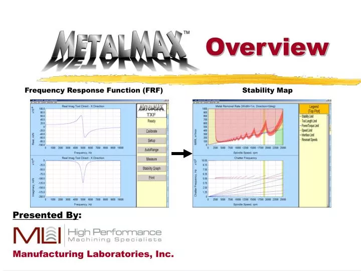
Overview. Frequency Response Function (FRF) Stability Map. Presented By : Manufacturing Laboratories, Inc. Purpose of Software. To predict, measure, avoid and control machining Vibrations. Uses common vibration measuring techniques.

E N D
Overview Frequency Response Function (FRF) Stability Map Presented By: Manufacturing Laboratories, Inc.
Purpose of Software • To predict, measure, avoid and control machining Vibrations. • Uses common vibration measuring techniques. • Applies them specifically to the machining process. Manufacturing Laboratories, Inc.
Problems With Today’s Machining (Dynamics) • All machines and tool stack-ups exhibit dynamic characteristics that will impact the cutting process. • Machining by definition is a dynamic process. • Dynamic Characteristics Limit Machining Performance (Ti vs AL). • These characteristics can vary significantly and can be difficult to predict reliably. Measurement is required. • Primary contributor for cutter failure, spindle failure, limits machining capabilities, etc. • Theory and understanding well known by many MR&D Depts. and Universities but only recently gaining awareness and acceptance on shop floors. Manufacturing Laboratories, Inc.
What Is High-Performance (HP) Machining? • There are many definitions: • Cutting speed • s(m/min)=pd(m/rot)n(rot/min) • Spindle speed or DN • DN = bearing bore diameter x spindle speed • Torque and Power • others • All of the definitions of high-performance machining are correct in some context. • High-Power is a natural artifact of high-speed. • Power = Torque x speed Manufacturing Laboratories, Inc.
Added considerations for High-Performance (HP) Machining • We have the additional influence of machining feed rates. • What is the “average” feed rate. • Chip-thinning • Surface area Manufacturing Laboratories, Inc.
What Limits HP-HS Machining Productivity? • Different types of machining operations have different limitations. • HP-HS machining may be limited by: • The onset of chatter • Tool-work piece materials • Available power • Tool geometry • Work piece geometry • Controller or servo performance (acc-dec) • Inadequate knowledge about machine capabilities Manufacturing Laboratories, Inc.
Chatter Limitations • Particularly in high speed operations where the objective is to have the metal removal rate as high as possible, the onset of chatter will be a limiting factor. • Chatter arises due to insufficient dynamic stiffness • Long slender tools • Small diameter spindles (DN limitation) • Flexible work pieces (although the selection of a tool path can avoid this in most cases) Manufacturing Laboratories, Inc.
Tool-Work piece Material Limitations • With work piece materials such as aluminum, the availability of a tool material is not a limitation. Tools are available which can tolerate the melting temperature of aluminum. • With hard steels, and even more so with titanium, maintaining acceptable tool life is a major problem. There has been some success with light cuts. Manufacturing Laboratories, Inc.
Power Limitations • In some cases where the machine-tool-work piece combination is dynamically stiff enough, the cutting operation may be limited by the available power. • Even for the stiffest machines, there are usually some tools which are not power limited. Manufacturing Laboratories, Inc.
Tool Geometry Limitations • In cases where the dynamic stiffness and power are sufficient, the cutting operation may be limited by the tool configuration (the length of the cutting edge or tool diameter, for example). • Cutting edge geometry may be dictated by material property characteristics, thermal behavior, shearing, etc. Manufacturing Laboratories, Inc.
Work piece Geometry • In some instances (many die and mold applications), the geometry of the cut is dictated by the desired work piece geometry. For example, the step-over dimension may be limited. In such cases, most of the machining can happen well below the available power. Manufacturing Laboratories, Inc.
Controller or Servo Performance Limitations • Especially for complex geometries, the block throughput rate of the controller can be a limiting factor. • Some easy tests exist • As the speed of the axis motions increase, the dynamic performance of the servos become more significant • High accelerations/decelerations (acc/dec) • Lightweight yet stiff moving elements • Look-ahead or feed forward control Manufacturing Laboratories, Inc.
Knowledge Limitations • A lack of understanding of high speed machine capabilities frequently leads to under-utilization of such machines. • A large, traditional experience base does not exist for high speed machine tool use. • Many high speed phenomena are counter-intuitive for users accustomed to conventional speed machines. • An acceptable part program is usually not the optimal part program. • The programmer needs the machine performance information at the time that the program is written. Manufacturing Laboratories, Inc.
3 Knowledge Possibilities Exist • You understand the performance capabilities of your machine very well and write part programs respecting the limitations. • Or • You fight chatter problems every day. • Or • You are under-utilizing your machine. Manufacturing Laboratories, Inc.
Which Qualities Of High-Performance High-Speed Machines Are Most Important? • Spindle Speed alone is not enough. • High power alone is not enough. • Fast motions or tool changes alone are not enough. • High performance controllers alone are not enough. • Advanced tool materials alone are not enough. • Certainly, these things are important, but….. Manufacturing Laboratories, Inc.
For reasons which will become apparent, the definition we will use is: “High-speed (HS-HP) machining occurs when the tooth passing frequency approaches the dominant natural frequency of the system”. -Scott Smith, UNCC Manufacturing Laboratories, Inc.
What Is Different About HP-HS Machining? • HP-HS machining is different from conventional machining, particularly in the strong influence of the dynamic characteristics of the machine-tool-work piece system on cutting performance. • In HP-HS machining, the metal removal rate (MRR) is usually limited by the onset of “chatter”. • Success in HP-HS machining depends heavily on the ability to recognize and deal with dynamic problems. • Selection of an appropriate spindle speed and depth-of-cut is extremely important and not obvious. Manufacturing Laboratories, Inc.
What Kinds of Parts Can Benefit From High Speed Machining? • Parts which have a large volume of material to be removed. • Aluminum and cast iron parts especially, but also hard materials such as dies and molds. • Parts with thin structures. • Parts which conventionally spend a long time on the machine either due to large metal removal or large surface areas to be machined. • Short runs, or frequently changed designs. • Many others. Manufacturing Laboratories, Inc.
Pocketed and Thin Section Parts Manufacturing Laboratories, Inc.
Monolithic Structures(formerly stack-ups) Manufacturing Laboratories, Inc.
Shop Floor Friendly Approach • Supply a complete solution to the problems with dynamics and machining. • Model and predict dynamic behavior • and its affect on the cutting process. • Effectively measure and adjust to • unexpected changes. • Maximize Cutting performance (MMR) • Simplify analysis of machine tools and cutters. • Distill technology down to its most essential parts (measurement and prediction). Machine a part right the first time! Manufacturing Laboratories, Inc.
Exactly what are we talking about? • Methods for obtaining information about the cutting process dynamics and quickly utilizing this information to maximize cutting performance. • Currently available by various means. • Applied in a way for maximum usability. • Our goal is to maximize metal removal rate and reduce or eliminate detrimental vibrations. • We want to utilize basic frequency analysis at the machine or on the shop floor (machinists, NC programmers, process planners, manufacturing engineers) to improve process setup, correct problems when they occur, and objectively evaluate performance. Manufacturing Laboratories, Inc.
What are we evaluating? • Design Parameters Frequency (fn), Stiffness (k) and damping (damping ratio ). They do not change over time or with load. • Dynamic stiffness (~2k) at Frequency (fn). • Sometimes we are concerned with the magnitude response, for cutting performance the negative real part of the FRF Frequency =fn Static Compliance Dynamic flexibility=~1/2k Negative Real Peak (chatter) Magnitude Response Real part of FRF Manufacturing Laboratories, Inc.
Why bother? • In a dynamic system component behaviors are highly interelated (e.g. everything affects everything). • Change one parameter and it is likely that the dynamic response will change, sometimes substantially. • Counter-intuitive behavior is inevitable. • Dynamic parameters, particularly damping can change. • All this will affect how much can be cut and how much the operation will vibrate (normally, resonate or chatter). Manufacturing Laboratories, Inc.
Fundamental Tool: Frequency Response Function (FRF) (20 mm 3-fluted Tool in 30 kW 24 krpm Spindle) Flexibility Manufacturing Laboratories, Inc.
Basis for Analysis:The Stability Lobe Diagram Process Damping Manufacturing Laboratories, Inc.
5 areas of machining Conventional Region High-Performance Region PoorMan Region Blim1 Blim2 – High-Speed Machining Manufacturing Laboratories, Inc.
5 Regions of Machining • Conventional • Typically Slow RPM with high Feed and DOC • Blim1 • Light DOC where all RPM are chatter-free, but not necessarily most robust • Blim2 – High-Speed Region • “industry accepted” low DOC high feed rate finishing • All RPM are chatter –free, but not necessarily most robust • PoorMan Region • Minimal or NO Sweet Spots, almost all RPM chatter • High-Performance Region • Largest Metal Removal Rates • Must select matching RPM and DOC Manufacturing Laboratories, Inc.
Desired Benefits • Promote Understanding • Explain Non-intuitive behavior, e.g. lobing diagram and the dynamics that produce it. • Guide user to Optimal Solution • Not necessarily looking for “precise” predictions but good guidance. • Fast Improvements • 90% results with 10% of the effort. • Clearly identify limitations, eliminate……….. “finger pointing” Manufacturing Laboratories, Inc.
What’s Needed? • Not as much as you may think. • Frequency Analyzer. • Widely available Sensors • Basic Cutting Theory • Commercial applications are becoming widely available that do not require the expertise of a “vibration expert”. MLI’s MetalMAX™ kit with computer. Manufacturing Laboratories, Inc.
Packages for Dynamic/Chatter Prediction and Control Measurement and Analysis Computation and Prediction Finite Element Spindle Analysis and Cutting Performance Analyzer Cutting Performance Analyzer for Machine Tools SPATM TXF™ Data Acquisition and Machining Analysis PCScope MilSimTM Milling simulation Verification and Tracking Track Data with particular setup, tool, machine, etc. Audio Monitoring of Cutting Process Harmonizer® CHiPSTM Manufacturing Laboratories, Inc. Page 5
How is it typically applied • Front Line Solutions • “TXF” • Chatter free speeds and power or depth of cut levels. • “Harmonizer®” • Audio monitoring and chatter detection and correction • Existing NC Program correction. • PCScope • Generic data collection • Track balance levels and spindle vibrations, temperatures. • Off-Line Solutions • MilSim and SPA • Off-line in-depth analysis. • Good NC-Programmer tool • CHiPS • Organize and track data. Manufacturing Laboratories, Inc.
Two Basic Approaches: “Trial and Error” and Predictive • Trial and Error • Similar to how we do it now in that we take test parts or run test work pieces and change things based on experience. • Additionally, we can integrate cutting theory and signal analysis to direct the changes more efficiently. • Predictive • Measure dynamics of tooling before cutting then compute behavior. • Simulate cutting and establish maximum parameters. • Verify results when implemented and have the ability to correct for subtle changes that may occur. Manufacturing Laboratories, Inc.
Predictive Approach. How do we do this? • Easiest way is called “impact” testing or modal analysis. • Use a hammer to excite the tool over a wide frequency range and and an accelerometer to measure the response and create an FRF (Frequency Response Function). • With proper software and setup measurement takes less than 5-minutes per tool. Manufacturing Laboratories, Inc.
Advantages and Disadvantages of Predictive Approach • Advantages: • Fast with minimal machine down time. • No requirement to run machine. • Flexibility to determine performance for all operation conditions. • Quick check for changes after “events”. • Disadvantages: • Limited accuracy depending on inputs. • Some technique and equipment needed Manufacturing Laboratories, Inc.
What is our concern. • Obviously the tool-work piece interface. • The flexibility and frequency behavior on the tool and on the part at the location of the cutting interface. • The entire machine and all its components contribute to this behavior but we are only concerned with how it is affecting just “ONE” location: Where cutting occurs (the cut interface). • We are only concerned with displacement for a given force, or the flexibility. Manufacturing Laboratories, Inc.
STRIKE Accelerometer Hammer PC Sensor Interface Module 4 Sensor Cable 3 RESPONSE 2 (ACCEL) EXCITATION 1 (HAMMER) Power Cable FRF Measurement with MetalMAX™ Equipment Schematic of Measurement Setup for TXF “Tap” or “Ping” test. Actual MetalMAX™ Equipment Manufacturing Laboratories, Inc.
Frequency Response Function to Cutting Performance (Analytical Solution, TXF) Chatter in red areas MRR Axis Chatter freqs. (in red) and resonant speeds Lobing Diagrams Provide MRR (Depth of Cut) and Spindle Speed values Measured Frequency Response Function (FRF) Manufacturing Laboratories, Inc.
General FRF Procedure • A FRF quantifies a tool’s “flexibility” frequency by frequency. • Excite system • Measure force • Measure response • Transform into frequency domain (Fourier Transform) • divide frequency by frequency • See video demonstration. • (PLUCKING A TUNING FORK) Manufacturing Laboratories, Inc.
Cutting Performance (TXF) Max Torque Max Power Stability Lobes Power Lobes Manufacturing Laboratories, Inc.
Advantages and Disadvantages of Trial and Error Approach • Advantages: • Most Accurate • Easy • Low skill level required • Software/hardware aids are commercially available, vibration meters, audio detectors, etc. • Disadvantages: • Time consuming • Consumes work piece material and tools and machine time. Manufacturing Laboratories, Inc.
Maximizing MRR with Width of Cut Increases Harmonized > 475% increase in Power and MRR Spindle Speed: 16,580 RPM Axial Depth of Cut 25 mm Radial width of cut 1.8 mm Cut Power 1.75 kW GREAT SURFACE!!! Spindle Speed: 20,000 RPM Axial Depth of Cut 25 mm Radial width of cut 0.25 mm Cut Power 0.3 kW BAD SURFACE Manufacturing Laboratories, Inc.
Knowledge of the spindle speed is essential. • Spindle speed components generally dominate the audio spectrum unless chatter is very severe. • Other audio sources are related to spindle speed, bearing passing frequencies, air-oil hiss, etc. • Correct setting of threshold maximizes sensitivity. Unfiltered Filtered Manufacturing Laboratories, Inc.
Trial and Error Example 10,000 RPM 8393 RPM Corner Cut, 10 mm deep, 12 mm wide Manufacturing Laboratories, Inc.
Trial and Error Example 10,000 RPM Frequency Content with no filters. 8393 RPM Frequency content no filters. Manufacturing Laboratories, Inc.
Milling Simulation • Simulation package needs measured dynamics as input. • Rapid more accurate solutions to speeds, depths of cut, feeds, cutting forces, tool deflection and surface error. • Include tooth run-out, imbalance, non-uniform pitch. • Excellent front-line, solution for process engineers and NC programmers. Manufacturing Laboratories, Inc.
Most Important: Cutting Tool Tracking and ControlThe CHiPS(TM) Database • To get the maximum payback each cutting tool assembly must be uniquely identified. • Machine, spindle, holder, cutter, manufacturer’s, stick out length’s, etc. must be tracked by either the customer tool management system or our customized Microsoft Access database for tool setup tracking with dynamics (CHiPS). • Record optimum speeds, feeds and depths of cut. • Based on measurement and calculation (TXF, MilSim™, etc.) and verified by cutting tests (Harmonizer). • Emphasize slotting information (the least stable case). • Data will not change unless a different tool, machine tool, or spindle is used. In fact results for identical model machines and spindles can be used on all machines of that model and spindle type. • Control of tool set up is required to insure database speeds, feeds, and DOC’s are valid (Dynamic repeatability and consistency). Manufacturing Laboratories, Inc.
CHiPS: Tracking all Tooling information Manufacturing Laboratories, Inc.
Is this Technology new? • No!, only in the way it is being applied. • Vibration measurement is very well developed. • Basic machining dynamic theory well-known for decades by academics and large corporate MR&D departments. • The process or practice is the focus rather than its affects. • Detect what is happening in the cut, not at the bearings, the motor, under the work piece, etc. • “Modal” Analysis or Frequency Analysis has been utilized extensively with the advent of the digital computer and algorithms. • Mostly in the design and product test areas. • To determine and measure resonance's (aircraft, autos, disk drives, etc.). • Even in the design of machine tools and components. • Spindle Rotor Analysis • Damping of fixtures Manufacturing Laboratories, Inc.
Is this all worth it? The Good News: YES! • PREDICTABLE and CONSISTENT: Well controlled setups will behave consistently. • Identical model machines even of different age will show minimal variation in frequency. • Stiffness will not change significantly over time. • Damping may change somewhat but its affects can be avoided. • PERFORMANCE IMPROVEMENTS: Stable cutting horsepower can generally be increased 50-200% or more compared to practically applied techniques. • COST AVOIDANCE: Tool life, time between spindle rebuilds, longevity of the machine, rotary table life, any machine component wear can generally see substantial (> 50%) improvements. Manufacturing Laboratories, Inc.