Download
1 / 65
650 likes | 753 Views
Improving Robustness of Inter-Autonomous OpenFlow Network by Extending its Control Model. Othman Othman M.M. , Koji Okamura Kyushu University Proceedings of the 33 nd Asia-Pacific Advanced Network Meeting Thailand , Chiang Mai, 2012/2/15. Outline:. Goal. Motivation.

E N D
Improving Robustness of Inter-Autonomous OpenFlow Network by Extending its Control Model Othman Othman M.M. , Koji Okamura Kyushu University Proceedings of the 33ndAsia-Pacific Advanced Network Meeting Thailand, Chiang Mai, 2012/2/15
Outline: • Goal. • Motivation. • An attempt to solve the problem • Network Equipment to Equipment flow installation. • Steps for Flow delegation. • Flow Aggregation Algorithm. • Finding Equipment . • Programming flows & Security aspect. • Tunneling. • Evaluation. • Conclusion.
1-Goal: • Improve OpenFlow. • Support self-reactive behavior. • Step towards having wider adoption of OpenFlow. • Reduce load on controller.
2-Motivation: • Tight coupling between OpenFlow switch and controller. • Every thing is up to the controller. • Controller might be bottleneck. • number of flows that can be installed by the NOX controller as shown in [1] are 30K flow/sec, and the flow arrival rate in [2] that is 100K flow per second. • Figures might have changed but debate still going. [1].Tavakoli, A., Casado, M., Koponen, T., & Shenker, S. (n.d.). Applying NOX to the Datacenter. Proc. HotNets (October 2009). [2]. Kandula, S., Sengupta, S., Greenberg, A., Patel, P., & Chaiken, R. (2009). The nature of data center traffic: measurements & analysis. Proceedings of the 9th ACM SIGCOMM conference on Internet measurement conference (p. 202–208). ACM.
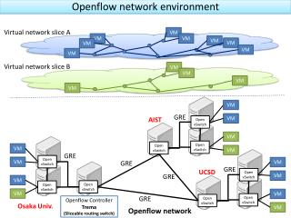
2- Motivation: Figure 1: OpenFlow Control Mode Figure 3: EnhancedOpenFlow Control Mode • Current OpenFlow’s control model: • Controller to Equipment only: Equipment exchange information only with the controller. • Current Internet: • Equipment to Equipment only: equipment exchange information with each other. • Target: • Controller to Equipment, AND Equipment to Equipment: to give OpenFlow the ability to exchange information between equipment in addition to controller. Fig2. Regular Network Information exchange.
2- Motivation: • Why Equipment to Equipment can help: • Network edges are suitable for installing flows, since all of the incoming and outgoing packets must pass through them. • Network edges can be used in different applications like, implementing security, traffic policies, traffic tagging, ….. • However, equipment flow table is limited. • Also Controller can be a bottleneck. • Equipment to Equipment Flow installation: • Provide a new method for the overloaded equipment to act on their own, without involving the controller.
3-An attempt to solve the problem: • Network equipment to Network equipment Flow Programming: • To create traffic-aware self-reactive network. • Can be used to delegate some flows to less loaded network equipment. • To easily program whole network without loading controller.
3- Network Equipment to Equipment flow installation : Flows to manipulate headers in packets P P Packet P Packet P P P Packet • To reduce load off the controller. • Give the equipment ability to act by their own to reduce load off loaded equipment. • Alternative way to install flows to whole network (e-e propagation). Packet Packet Packet Fig1. Equipment overloaded, due to many flows to carry out. Packet P Packet PE Packet PE PE P P Fig2. Overloaded equipment delegates some flows to other equipment. Flows to manipulate headers in packets Fig3. Reduced load off the overloaded equipment.
4- Steps for Flow delegation : 1 Start No 2 Need to delegate? Yes Find aggregate able flows. And aggregate them. 3 Find equipment to program. 4 5 Program flows from 3 to equipment form 4 Tunnel aggregated flows from 3 to target equipment form 4. 6 7 Finish
4- Steps for Flow delegation :1-Flow Aggregation Algorithm : Flow Table • How to delegate flows? • Aggregate flows that have common features, and responsible for some portion of traffic. • i.e. to aggregate many flows to one. • Delegate the aggregated flows to other equipment. • Use Flow Aggregation Algorithm. • Overloaded equipment flows = original flows – delegated flows. Range of portions of total traffic e.g. (20%-30%) Flow Aggregation Algorithm aggregated flow (one or more)
4-Steps for Flow delegation: 1- Flow Aggregation Algorithm : Start Build Histograms for all Fields • TA-FAA : • TA-FAA Evaluation: • Java Program to evaluate the efficiency of Flow Aggregation Algorithm. • FAA success rate of aggregation = 79.7 % None Aggregation percentage? Strict Wide Aggregate SrcIP None Strict Wide Aggregate DstIP None Strict Wide Find commonvalues from two wide aggregations. None, Wide Strict Fail Finish
4: Steps for Flow delegation2- Finding Equipment : • Request is a kind of controlled flooding: • Limited propagation; request will have a count to valid hop counts.(TTL) • Limited number of acceptance, (LFI); Level of Flow Installation. • Negative Acknowledgement. • Expiry time. • 3 way programming method: • Request, Accept, Confirm • Request is a kind of controlled flooding. The delegating device The device receiving delegation Other device receiving delegation • Installation Request? • Flows to be delegated. • LFI= 2 , TTL=5 • Accept • Self Identification. • Installation Request? • Flows to be delegated. • LFI= 1 , TTL=4 Confirm • Accept • Self Identification. Confirm
4: Steps for Flow delegation3- Programming flows & Security aspect : 1 Flow 1 1 Figure 1: Initial Flow Installation. 3 Figure 2: Flow Delegation (e-e Flow Installation) 2 2 2 Request Flow Req. hash 2’s ID Flow 1’s ID Signed by Controller Flow’s Hash 2’s ID Signed by Equipment 1 Signed by Equipment 2
4: Steps for Flow delegation3- Programming flows & Security aspect : • Why to do that: case of flow includes sending packet to controller Flow 1 1 1 Flow Figure 2: This flow was delegated. Figure 1: Controller installs flow. Figure 3: Accepting packets form eq.2 instead of eq.1. 1’s ID 2 2 2 Flow’s Hash 2’s ID Flow Expect packet from eq.1 Expect packet from eq.1 Expect packet from eq.1 eq.2 used the signed fields it got form eq.1 So controller will accept Signed by Controller Signed by Equipment 1 Signed by Equipment 2
4: Steps for Flow delegation4- Tunneling : Flow Flow Flow Flow • In such cases: • eq.4 have to tunnel packets to eq.2. • This is done using IP tagging . (similar to VLAN tag) • Also eq.1 uses the aggregated flow (1 flow) to tunnel traffic to eq.4. Flow Flow 2 3 1 4 Fig1. flows are stitched to form a path defined by controller. Fig2. Path might break because eq.2 expects packets from eq.1 or the interface of eq.2 that connects it to eq.1. 2 3 1 4
5- Evaluation: • Run simulation on NS3 using : • Regular OpenFlow. • Modified OpenFlow. • Collaboration for experimenting on NICT’s JGN-X. • Compare edge equipment load, all equipment load. • Evaluate efficiency to reduce load. • Evaluate traffic generated by the new enhancement.
6- Conclusion: • Aim to improve OpenFlow by reducing load off the controller, make it self-aware and self-reactive,. • Achieving goals by proposing a new enhancements to OpenFlow: • Network equipment to equipment flow installation. • Proposing Flow Aggregation Algorithm, to enable the enhancements. • Simulation shows the success rate of FAA is 79.7 %
Q & A: • Thanks for listening.
3- OpenFlow Overview: • Separates routing decision making (in controller) and the forwarding (in the switch or router). • Matching in the switch or router is done according to Layer 2, 3 and VLAN headers. Figure 1: OpenFlow switch (ref: Nick McKeown et al, “OpenFlow: enabling innovation in campus networks”)
3- OpenFlow Overview: • OpenFlow relies on the Flow-table, which is contains: • Header fields are the ones the incoming packet is matched against: • The actions can be : forwarding the packet to physical port, enqueue the packet in a physical port’s queue, dropping the packet or modifying incoming packet’s header fields Figure 1 Figure 2
6- First: Network Equipment to Equipment flow installation: Fig1. Regular way of installing flows. Controller installs to equipment one by one. Fig2. Network equipment install flows to each other. • To reduce load off the controller. • Alternative way to install flows to whole network (e-e propagation). Controller Controller
7- Second: Low Level Header Description: • OpenFlow can deal with headers of: • Ethernet • IP • TCP • UDP • ICMP • ARP • VLAN • This limits the usage to those protocols. Fig1: Flowchart showing how header fields are parsed for matching. As shown in : OpenFlow Switch Specification Version 1.0.0, December 31, 2009
8- Third: Inactive Flows: • Initially installed as inactive. (not usable). • Activated on right time to use by: • Explicit activation packet. • Activation Flow. • Preset time. • Can use e-e for activating other equipment. Server 10.10.10.1 Server 10.10.10.1 Candidate Server Candidate Server Server 10.10.10.1 Candidate Server Fig2. Programming inactive redirection And migrating server. Activating redirection when migration finishes Fig1. Before beginning Fig3. After migration and activation of redirections. Server Migration
8- Third: Inactive Flows: • Original OpenFlow: flows are activated by default (usable as soon as programmed). • Controller have to install redirections exactly on time for time-critical applications. • case of server migration. Fig1. Migration and Redirection using OpenFlow. Fig2. Delay due to controller overload in Migration and Redirection using OpenFlow. Migration Migration Migration Migration ?
Start Start Build Histograms for all Fields Build Histograms for all Fields None None Strict Strict Aggregation percentage? Aggregation percentage? Wide Wide Aggregate SrcIP Aggregate SrcIP Strict Strict None None Wide Wide Aggregate DstIP Aggregate DstIP None None Strict Strict Wide Wide Find commonvalues from two wide aggregations. Find commonvalues from two wide aggregations. None, Wide None, Wide Strict Strict Finish Finish Fail Fail
4-1-Introduction about flow aggregation algorithm (FAA). original flows (large #) • Goal: • To represent a large # of flows (original) by a single or few flows (aggregated). • In order to replace the original flows (large #) by the aggregated flow (one or more). • Assign the original flows (large #) to another network equipment. Flow Aggregation Algorithm aggregated flow (one or more)
3-An attempt to solve the problem: Figure 1: OpenFlow Control Mode • Current OpenFlow’s control model: • Controller to Equipment only: Equipment exchange information only with the controller. • Current Internet: • Equipment to Equipment only: equipment exchange information with each other. • Target: • Controller to Equipment, AND Equipment to Equipment: to give OpenFlow the ability to exchange information between equipment in addition to controller.
5- Inputs of the FAA. Flow Table • Input is Flow Table. • Flow table entry have one or more fields form Fig 1. • Src IP and Dst IP can be wildcarded as defined by OpenFlow Range of portions of total traffic e.g. (20%-30%) Flow Aggregation Algorithm aggregated flow (one or more) Fig1: Fields from packets used to match against flow entries As shown in : OpenFlow Switch Specification Version 1.0.0, December 31, 2009
5-Outputs of the FAA. Flow Table • Aggregated Flow can use: • Parts of Src IP, Dst IP using wildcards. • Any other field as an exact match. Range of portions of total traffic e.g. (20%-30%) Flow Aggregation Algorithm aggregated flow (one or more) Fig1: Fields from packets used to match against flow entries As shown in : OpenFlow Switch Specification Version 1.0.0, December 31, 2009
5-Details of the FAA. Start Build Histograms for all Fields None Strict Aggregation percentage? Wide Aggregate SrcIP Strict None Wide Aggregate DstIP Wide Strict Find commonvalues from two wide aggregations. None, Wide Strict None Finish Fail
5- Evaluation: Start Start Build Histograms for all Fields Build Histograms for all Fields • TA-FAA : • TA-FAA Evaluation: • Java Program to evaluate the efficiency of Flow Aggregation Algorithm. • FAA success rate of aggregation = 79.7 % None Strict Aggregation percentage? None Aggregation percentage? Strict Wide Wide Aggregate SrcIP Aggregate SrcIP Strict None None Strict Wide Wide Aggregate DstIP Aggregate DstIP None Wide Strict Strict Wide None Find commonvalues from two wide aggregations. Find commonvalues from two wide aggregations. None, Wide Strict None, Wide Strict Fail Finish Finish Fail
6- Some aspects of Flow delegation: • Security: • When requesting for delegation. • Controller signs all flows. • Equipment identify source of flows is controller. • Equipment to request delegation also sins request, that incudes flows to be delegated and a time out value. • Equipment identify equipment that requested the delegation. • Time out to reduce effect of attacks.
6- Some aspects of Flow delegation: • Security: • When the delegated equipment needs to send to the controller. Controller must be able to tell if the flows can be trusted. • Controller signs all flows. • Equipment identify source of flows is controller. • Equipment to request delegation also sins request, that incudes flows to be delegated and a time out value. • Equipment identify equipment that requested the delegation. • Time out to reduce effect of attacks. • Equipment that accepts request will send a signed hash valued of the delegated flows, along with its OpenFlow ID. • Delegation requester will receive the ID of the accepter and authenticate its sender. • Requester will send back to accepter: a signed (has for each flow, signature of controller, signature of requester, receiver ID). • Accepter when sending to controller will use the previous signed values for the first time
3- Equipment flow installation: Flows to manipulate headers in packets P P Packet P Packet P P P Packet • To reduce load off the controller. • Give the equipment ability to act by their own to reduce load off loaded equipment. • Alternative way to install flows to whole network (e-e propagation). Packet Packet Packet Fig1. Equipment overloaded, due to many flows to carry out. Packet P Packet PE Packet PE PE P P Fig2. Overloaded equipment delegates some flows to other equipment. Flows to manipulate headers in packets Fig3. Reduced load off the overloaded equipment.
Improving Robustness of Inter-Autonomous OpenFlow Network by Extending its Control Model Othman Othman M.M. , Koji Okamura Kyushu University Proceedings of the 33ndAsia-Pacific Advanced Network Meeting Thailand, Chiang Mai, 2012/2/15
Outline: • Goal. • Motivation. • An attempt to solve the problem (3 enhancements). • First: Network Equipment to Equipment flow installation. • Second: Low Level Header Description. • Third: Proactive Flows. • Flow Aggregation Algorithm. • Evaluation. • Conclusion.
1-Goal: • Improve OpenFlow. • Support self-reactive behavior. • Step towards having wider adoption of OpenFlow. • Reduce load on controller.
2-Motivation: • Tight coupling between OpenFlow switch and controller. • Every thing is up to the controller. • Controller might be bottleneck. • number of flows that can be installed by the NOX controller as shown in [1] are 30K flow/sec, and the flow arrival rate in [2] that is 100K flow per second. • Figures might have changed but debate still going. [1].Tavakoli, A., Casado, M., Koponen, T., & Shenker, S. (n.d.). Applying NOX to the Datacenter. Proc. HotNets (October 2009). [2]. Kandula, S., Sengupta, S., Greenberg, A., Patel, P., & Chaiken, R. (2009). The nature of data center traffic: measurements & analysis. Proceedings of the 9th ACM SIGCOMM conference on Internet measurement conference (p. 202–208). ACM.
3-An attempt to solve the problem:(3 enhancements) • Network equipment to Network equipment Flow Programming: • To create traffic-aware self-reactive network. • Can be used to delegate some flows to less loaded network equipment. • To easily program whole network without loading controller. • Low level description of Headers: • To easily adopt new protocols. • To be able to program flows in very exact way. • New type of Flows: • Programed as inactive flows and later activated by the flow. • To provide the controller with a more relaxed way to handle precisely timed tasks. • Can cooperate with Device to Device programming.
3-1- First: Network Equipment to Equipment flow installation: Flows to manipulate headers in packets P P Packet P Packet P P P Packet • To reduce load off the controller. • Give the equipment ability to act by their own to reduce load off loaded equipment. • Alternative way to install flows to whole network (e-e propagation). Packet Packet Packet Fig1. Equipment overloaded, due to many flows to carry out. Packet P Packet PE Packet PE PE P P Fig2. Overloaded equipment delegates some flows to other equipment. Flows to manipulate headers in packets Fig3. Reduced load off the overloaded equipment.
3-2- Second: Low Level Header Description: • OpenFlow can deal with headers of: • Ethernet, IP, TCP, UDP, ICMP, ARP, VLAN • This limits the usage to those protocols. • Using Low level definition of header fields can be more usable in case of new protocols. Fig2: Low level description of headers Fig1: Fields from packets used to match against flow entries As shown in : OpenFlow Switch Specification Version 1.0.0, December 31, 2009
3-3- Third: Inactive Flows: • Original OpenFlow’s flows: • flows activated by default. • i.e. they will work as soon as they are installed. • So controller must keep track of time. • Figure 1 shows how a controller can support migration. • Figure 2 shows what might happen if the controller was overloaded and failed to install the redirection flows on the right time. Fig1. Migration and Redirection using OpenFlow. Fig2. Delay due to controller overload in Migration. Migration Migration Migration Migration ?
3-3- Third: Proactive Flows: • Original OpenFlow’s flows: • flows activated by default. • i.e. they will work as soon as they are installed. • So controller must keep track of time. • Proposed Proactive Flows: • Initially installed as inactive. (not usable). • So that those flows can be installed ahead of time. • Then activate on right time, by: • Explicit activation packet. • Activation Flow. • Preset time. Fig3. Migration and Redirection using OpenFlow and Inactive Flows. Inactive Flows Migration Flows activation Migration
4-1- Flow Aggregation Algorithm: Introduction: Flow Table • How to delegate flows? • Aggregate flows that have common features, and responsible for some portion of traffic. • i.e. to aggregate many flows to one. • Delegate the aggregated flows to other equipment. • Use Flow Aggregation Algorithm. • Overloaded equipment flows = original flows – delegated flows. Flow Aggregation Algorithm aggregated flow (one or more)
4-2- Inputs of the FAA. Flow Table • Input is Flow Table. • Flow table entry have one or more fields form Fig 1. • Src IP and Dst IP can be wildcarded as defined by OpenFlow Flow Aggregation Algorithm aggregated flow (one or more) Fig1: Fields from packets used to match against flow entries As shown in : OpenFlow Switch Specification Version 1.0.0, December 31, 2009
4-3-Outputs of the FAA. Flow Table • Aggregated Flow can use: • Parts of Src IP, Dst IP using wildcards. • Any other field as an exact match. Range of portions of total traffic e.g. (20%-30%) Flow Aggregation Algorithm aggregated flow (one or more) Fig1: Fields from packets used to match against flow entries As shown in : OpenFlow Switch Specification Version 1.0.0, December 31, 2009
4-4-Details of the FAA. Start Build Histograms for all Fields None Strict Aggregation percentage? Wide Aggregate SrcIP Strict None Wide Aggregate DstIP Wide Strict Find commonvalues from two wide aggregations. None, Wide Strict None Finish Fail
4-5-In-depth look:1- IP aggregation: Start Start 1 Build Histograms for all Fields Add the most significant bit of each IP in each flow to trie. If exist increment trie node counter. Else create node and increment counter • By Building a Trie. • Find length of wildcard. • Value of wildcarded IP. None Strict Aggregation %? 2 Wide Aggregate SrcIP Is aggregation successful? Yes Strict None 3 Wide Aggregate DstIP No Add the next less significant bit of each IP in each flow to trie. If exist increment trie node counter. Else create node and increment counter Is memory limit reached? None 4 No Strict 5 Wide Find commonvalues from two wide aggregations. Yes Mark the trie node that has the best ratio . 6 None, Wide Finish 7 Strict Finish Fail
4-6-In-depth look:2- Other aggregation: Start Build Histograms for all Fields • By building Histogram. Start 1 None Strict Aggregation %? Build Histogram 2 Wide Aggregate SrcIP Is aggregation successful? Strict None 3 Wide No Aggregate DstIP Yes Find nodes with right aggregation ratio None 4 Strict Wide Finish 7 Find commonvalues from two wide aggregations. None, Wide Strict Finish Fail