Download
1 / 37
370 likes | 379 Views
This document outlines the commissioning plans for the laser system in the injector with spectrometer at 135MeV, including parameters, tuning, diagnostics, start-up, and alignment. It also discusses critical measurements and the key software and data analysis tools used.

E N D
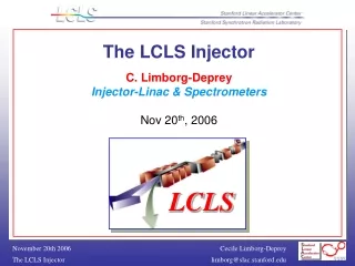
Injector Commissioning PlansC.Limborg-Deprey Parameters nominal tuning 1nC 0.2nC Diagnostics Start-Up and Alignment Calibrations + Critical Measurements Gun : Spectrometer 135MeV : Emittance, Spectrometers Key Softwares Data Analysis Softwares On-Line Modeling Tools
Injector-Linac Installation • Laser System June 2006 • Gun Region April 2006 • Accel Region March 2006 • Heater Region January 2006 • Wall Region October 2005 • Injection Region August 2006 • Spect Region August 2006 Commissioning starts Jan07 August07
Alcove : feet underground Sector 20 Alcove Laser Bay Drive Laser Drive Laser System Transport Tubes Transport Tube Laser Heater RF Gun Laser Heater UV Launch and Condition. Photocathode Gun & Launch System Electron Diagnostic Courtesy J.Mitchell
Critical parameters assessed at GTF thermal = 0.6 mm.mrad per mm laser spot size measured for S-Band copper cathode (discrepancy to theoretical thermal value is under investigation) E peak = 120MV/m QE = 3.10-5 Alternate tuning 0.2 nC Performances demonstrated at GTF (slice~ 1mm.mrad without laser shaping) With laser pulse shaped, much better performances expected Tuning easier for whole LCLS (reduced wakefields …) Parameters
6 MeV = 1.6 m ,un. = 3keV 63 MeV = 1.08 m ,un. = 3keV 135 MeV = 1.07 m ,un. = 3keV 135 MeV = 1.07 m ,un. = 40keV Linac tunnel ‘Laser Heater’ DL1 Gun S1 S2 L0-2 24 MV/m L0-1 19.8MV/m Spectrometer 3 screen emittance measurement ‘RF Deflecting cavity’ TCAV1 Spectrometer UV Laser 200 J, = 255 nm, 5-20 ps, r = 0-1.5 mm
Current Monitors Wire scanners OTRs Cerenkov Radiator EO monitor Gun Spectrometer Straight Ahead Spectrometer Diagnostics YAGs
Start-Up Steering + Stability + Shape Temporal Transverse • Laser Commissioning • Deliver laser to linac vault • Steer beam through transport tubes and set up alignment fiducials • Set up laser BPM and measure laser beam spatial jitter • Test laser energy diagnostic and vary laser energy from 1-100 mJ at cathode • Test laser timing diagnostic (ns diode or comparable detector) • Set up and test the laser virtual cathode • Measure laser pulse length with streak camera • Measure at cathode position without cathode. • Test ability to adjust pulse length from 2-10 ps • Vary laser beam diameter at cathode from 100 microns to 2 mm. • Gun Commissioning • RF processing • Measure following parameters as a function of rf field (power) at 10 Hz stop when the field on axis as measured with the field probes is 130 MV/m. • Gun Probe amplitude signals • Gun forward power signals • Gun Probe phase signals • Dark current • Vacuum levels • Gun Temperature • Reflected power pulse shape • klystron voltage • Decrease field to 120 MV/m and increase rep rate slowly while monitoring gun probe signals (amplitude and phase) and reflected power signal for change in shape or amplitude • Laser and RF Timing • Measure the gun Probe RF amplitude signal and photodiode signal vs time • Add delay as necessary to trigger laser at desired time during rf signal RF Processing Laser Timing Courtesy J.Schmerge
BBA • BBA of solenoid • align centers of • laser beam – Gun – solenoid – linac • Steerers in solenoid + SC1 (0.8m)+SC2(1.5m) • Do we need remote control ? • still under discussion in our group • hope to get information from M.Krasilnikov presentation • BBA • BPMs offsets (Quad Shunt)
Including Magnets Treaty Point
1 2 4 3 Linac tunnel ‘Laser Heater’ Straight Ahead Spectrometer 3 screen emittance measurement ‘RF Deflecting cavity’ TCAV1 Emission thermal Uniformity QE Gun Spectrometer
2 1 Thermal emittance Uniformity Emission Spot YAG1 YAG2 CR1 Energy Energy Spread Temporal uniformity Time-Space correlation Slice thermal emittance YAGG1 rf Vrf Bsolenoid CRG1
1 Emission • QE • Cathode imaging • Point-to-Point Imaging • Transverse uniformity of emission disk • Ellipticity + Slope of Edges • Thermal emittance measurement • Infinite-to-Point imaging • Divergence at cathode • Model thermal emittance • Future “optimal pulse shaping” (3D-ellipsoid) • Measure time-radius correlation • Dephasing of RF Gun • Good thermal emittance model is fundamental for experiment/simulations
Schottky Scan J.Schmerge, GTF
Laser masking of cathode image at DUVFEL Above: Laser cathode image with mask removed showing smooth profile. Below: Resulting electron beam showing hot spot of emission. Above: Laser cathode image of air force mask in laser room. Below: Resulting electron beam at pop 2. Courtesy W.Graves
Thermal emittance • At YAG2 • With low accelerating gradient Good resolution Assumes th = 0.6 mm.mrad Good resolution (better than at YAG1) YAG2 == Image of divergence of source
Imaging source divergence what type of momentum distribution?
Difficulties of Calibrations • beam atYAG1 varies with Vrf , rf , Gun field balance, charge, Solenoid calibration • calibrate Vrf , rf (see slide 21-22) • rotation of L-shape mask • then can possibly detect field unbalanced Fit of DUVFEL measurements
2 Gun Spectrometer • Energy • Absolute energy • alignment using laser • spectrometer field calibration • Lifts-up rf Vrf • Correlated Energy Spread for all charges • Uncorrelated energy spread for low charges • Introducing a time-energy correlation (varying injection phase) • Slice thermal emittance • Relay imaging system from YAG1 to spectrometer screens • Point-to-point imaging in both planes • Uniformity of line density • 3D-ellispoid Emission pulse
Calibrations, Orthogonality of knobs Rotation of L-shape mask Vrf Steering coil (2), offset at YAG1/YAG2 Spectrometer calibration Shottky scan (for short bunch ~2ps) rf Shottky scan at different gun fields Energy spread at low/high current in spectrometer Solenoid Beam size compared at YAG1 / YAG2 Waist vs charge Gun Balance Offset in solenoid scan curve Direct field measurement from probes
Orthogonality rf Vrf • Energy vs Phase (for different Vrf) • Current vs charge Operating point = 2 from minimum E Zero Current
Orthogonality rf Vrf • With finite bunch length
Direct measurement of E vs rf Low Charge operation Gun spectrometer with all quadrupoles off Referenced to nominal = 32 Referenced to nominal = 32
1nC Nominal tuning – no quadrupole on - High Charge operation Longitudinal at YAG1 YAGG1 YAGG1
High Charge operation • Correlated Energy spread vs rf • Calibration rfrepeated At YAG1 At YAGG1 PARMELA Simulations for 1 nC Good Linearity
High Charge operation 1nC, temporal pulse … at YAG1 location 8% modulation Nominal phase Quadrupoles off YAG1
Temporal pulse , … using quadrupoles to project on manageable size screen High Charge operation RF Quadrupoles on Resolves modulation at YAG1 location
More Profile measurement Standard “Beer Can” “3D-Ellipsoid”
Laser Heater Transverse RF Cavity OTR Emittance Screens 3 DL1 Bend Straight Ahead Spectrometer Straight Ahead Spectrometer
Longitudinal Phase Space at waist • Transverse deflecting cavity y / time correlation • (0.5mrad over 10ps ) • Spectrometer x / energy correlation • Direct longitudinal Phase Space representation rms From PARMELA simulations (assuming 1m emittance), resolution of less than 10 keV
Straight Ahead Spectrometer • Tuned to possibly be used in pulsed mode • Laminated magnet + ceramic chamber Dx ~ 1m x ~0.1 Same tuning
4 sy bunch length RF-deflector at 1 MV Slice-Emittance Measurement Simulation slice OTR 10 times quad scanned Courtesy P.Emma
= meas. sim. = calc. = y distribution = actual (slice-y-emittance also simulated in BC1-center) Slice-Emittance Measurement Simulation Injector at 135 MeV with S-band RF-deflector at 1 MV (same SLAC slice-ecode used at BNL/SDL) slice-5 Courtesy P.Emma
Conclusions • Diagnostics were designed to provide • Tools for performing correctly emittance compensation • 6D characterization of beam at end of injector • Diagnostics for degraded beam started • Temporal Modulation laser • Large emittance => Energy spread measurement ok • On-line simulations tools to be chosen • Fast-tracker (Homdyn, Trace3D, PARMELA …??…) • MP tracker (PARMELA, ASTRA, IMPACT, GPT …??…)
Including Magnets Treaty Point Straight Ahead Spectrometer 3 screen emittance measurement ‘RF Deflecting cavity’ TCAV1 Gun Spectrometer
Diagnostics Current Monitors Straight Ahead Spectrometer Wire scanners Cerenkov Radiator OTRs YAGs Gun Spectrometer EO monitor
Low Charge Operations 1 nC 2.8 kA • Need 20% smaller emittance (0.8 mm), but with 1/5 charge & 1/3 gun current (30 A) • No more transverse wakes in linac • Almost no CSR in BC’s • 2-times less peak-current jitter • No undulator wakes • 3-times shorter X-ray pulse • 1-nC still OK, but only ~twice the photons, and a much more challenging machine 0.2 nC 2.0 kA no spikes 1.11012 photons no resistive wake W. Fawley, LBNL Z. Huang