Download
1 / 22
240 likes | 827 Views
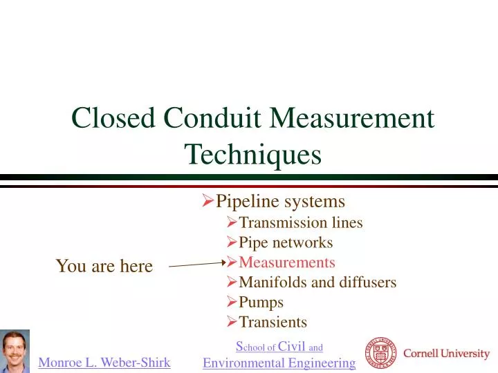
Closed Conduit Measurement Techniques. Pipeline systems Transmission lines Pipe networks Measurements Manifolds and diffusers Pumps Transients. You are here. Direct Volume or Weight measurements Velocity-Area Integration Pressure differential Pitot Tube Venturi Meter Orifice

E N D
Closed Conduit Measurement Techniques Pipeline systems Transmission lines Pipe networks Measurements Manifolds and diffusers Pumps Transients You are here
Direct Volume or Weight measurements Velocity-Area Integration Pressure differential Pitot Tube Venturi Meter Orifice Elbow Meter Electromagnetic Flow Meter Turbine Flow Meter Vortex Flow Meter Displacement Meter Ultrasonic flow meter Acoustic Doppler Laser Doppler Particle Tracking Measurement Techniques
Some Simple Techniques... • Direct Volume or Weight measurements • Measure volume and time (bucket and stopwatch) • Excellent for average flow measurements • Velocity-Area Integration Stream flow
V Pitot Tube Stagnation pressure tap Static pressure tap 2 0 V1= 1 z1= z2 Connect two ports to differential pressure transducer. Make sure Pitot tube is completely filled with the fluid that is being measured. Solve for velocity as function of pressure difference
1 2 Venturi Meter • 1797 - Venturi presented his work on the Venturi tube • 1887 - first commercial Venturi tube produced by Clemens Herschel • Minimal pressure loss Contraction Yes! Bernoulli equation applicable?_______ Why?
1 2 Venturi Meter Discharge Equation Cv is the coefficient of velocity. It corrects for viscous effects (energy losses) and velocity gradients (a). Kventuri is 1 for high Re and small D2/D1 ratios
8 D Orifice 2.5 D Dh D The flow coefficient, Korifice, is a function of the ratio of orifice diameter to pipe diameter and is a weak function of ________ number. Reynolds
Elbow Meter • Acceleration around the bend results in higher pressure at the outside of the bend • Any elbow can be used as the meter • Needs to be calibrated (no standard calibration curves are available)
Electromagnetic Flow Meter • Conductor moving through a magnetic field generates an _______ field. • Voltage is proportional to velocity • Causes no __________ resistance to flow • High signal amplification is required magnet conductive fluid electric electrodes “measurable” measure voltage here
Turbine and Paddle Wheel Flow Meters • Simply a turbine mounted in a pipe held in a stream • The angular velocity of the turbine is related to the velocity of the fluid • Can operate with relatively low head loss • Needs to be calibrated • Used to measure _________ ___ ____ or___________ volumetric flow rate velocity
Vortex Flow Meter • Vortex shedding • Strouhal number, S, is constant for Re between 104 and 106 • Vortex shedding frequency (n) can be detected with pressure sensors d L
Displacement Meter • Used extensively for measuring the quantity of water used by households and businesses • Uses positive displacement of a piston or disc • Each cycle of the piston corresponds to a known volume of water • Designed to accurately measure slow leaks!
Ultrasonic Flow Meters:Doppler effect • The transmitted frequency is altered linearly by being reflected from particles and bubbles in the fluid. The net result is a frequency shift between transmitter and receiver frequencies that is proportional to the velocity of the particles. Doppler shift Sound velocity Transmitted frequency http://www.sensorsmag.com/articles/1097/flow1097/main.shtml
Ultrasonic Flow Meters:Transit Time • Measure the difference in travel time between pulses transmitted in a single path along and against the flow. • Two transducers are used, one upstream of the other. Each acts as both a transmitter and receiver for the ultrasonic beam.
Acoustic Doppler Velocimeter http://www.sontek.com/ Point _______ measurement
Laser Doppler Velocimetry • a single laser beam is split into two equal-intensity beams which are focused at a point in the flow field. • An interference pattern is formed at the point where the beams intersect, defining the measuring volume. • Particles moving through the measuring volume scatter light of varying intensity, some of which is collected by a photodetector. • The resulting frequency of the photodetector output is related directly to particle velocity. • _______ measurement http://www.tsi.com/ Point
Particle Tracking Velocimetry • Illuminate a slice of fluid (seeded with particles) with a laser sheet • Take a high resolution picture with a digital camera • Repeat a few milliseconds later • Compare the two images to determine particle displacement • Measures _______ ______ velocity field http://amy.me.tufts.edu/
Questions to Ponder • Will an ADV need to be recalibrated if it is moved from freshwater to saltwater? • A graduate student proposes to use an LDV in a wave tank (through a glass bottom) that is stratified with freshwater on top of saltwater to measure turbulence from the breaking waves. What problems might arise? • How could the flow normal to the plane of the light sheet be estimated using PTV? • Would it be possible to know the direction of the flow in the 3rd dimension?
More Questions to Ponder • Why would a flow meter manufacturer specify that the pipe used for installing the meter must be straight for 10 diameters upstream and 5 diameters downstream from the meter? • How could an ultrasonic device get information about velocity at more than one location without moving (profiling)? • How could you apply the results from profiling to improve the flow rate measurement in a pipe?
Orifice Example • Estimate the orifice diameter that will result in a 100 kPa pressure drop in a 6.35 mm I.D. pipe with a flow rate of 80 mL/s. The orifice coefficient (Korifice) is 0.6. • What is the ratio of orifice diameter to pipe diameter? • If the smallest pressure differential that can accurately be measured with the pressure sensor is 1 kPa, what is the smallest flow that can accurately be measured using this orifice? • What are two ways of extending the range of measurement to lower flows?
Orifice Solution • Estimate the orifice diameter that will result in a 100 kPa pressure drop in a 6.35 mm I.D. pipe with a flow rate of 80 mL/s. The orifice coefficient (Korifice) is 0.6.
Orifice Solution • What is the ratio of orifice diameter to pipe diameter? • If the smallest pressure differential that can accurately be measured with the pressure sensor is 1 kPa, what is the smallest flow that can accurately be measured using this orifice? • What are two ways of extending the range of measurement to lower flows? (0.546) 8 mL/s


![[TC]²: Redefining Measurement Techniques](https://cdn4.slideserve.com/8405313/tc-redefining-measurement-techniques-dt.jpg)