Download
1 / 19
190 likes | 365 Views
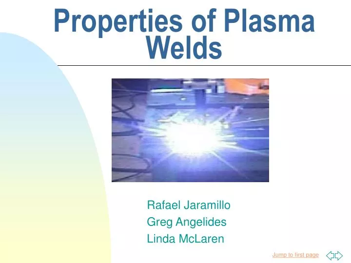
Properties of Plasma Welds. Rafael Jaramillo Greg Angelides Linda McLaren. Overview. Experimental Objectives and Motivation Previous Work Experimental Design Results Future Work. Objectives and Motivation. Create a complete database of plasma welds

E N D
Properties of Plasma Welds Rafael Jaramillo Greg Angelides Linda McLaren
Overview • Experimental Objectives and Motivation • Previous Work • Experimental Design • Results • Future Work
Objectives and Motivation • Create a complete database of plasma • welds • Study how speed and amperage affect the • weld attributes. • - width • - depth • - structure • Determine whether temperatures read with • a thermocouple correlate with Infrared • Camera readings.
1.5 mm/s 2.0 mm/s 3.0 mm/s 4.0 mm/s 4.5 mm/s 5.0 mm/s 1.5 mm/s 2.0 mm/s 3.0 mm/s 4.0 mm/s 4.5 mm/s Previous Work Two years ago an REU group created several plasma welds. Last year’s group organized them.
Experimental Setup Fluke + Computer Plasma Welding Robot Camera Control + Television Infrared Camera Sample Holder
Experimental Design • Samples were cut and cleaned • Thermocouples were affixed • Sample was welded at specified current and speed • Temperature Data was recorded using a Fluke Hydra DAQ unit.
Infrared Recordings were made during welding. • Cross sectional cut of samples was made and put into molds for microscope study.
Polishing! • 5 step polishing process • Fine polishing necessary for viewing microscopic structures
Finding IR Camera Range • Temp. range of IR camera had to be set before welding process • Tradeoff between visible temperature range and temperature resolution • Range set at 200 – 700 oC • Entire heating process could not be captured
Sources of Error • Unreliable thermocouples: ultrasonic welding process flattened the leads • IR data could not be taken at thermocouple’s exact location • IR camera pixel intensity found to be unreliable
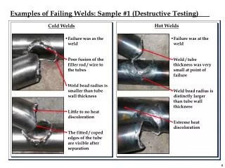
Thermocouple Problem Good weld Bad weld
Future Work • Examine samples under microscope for structural changes due to welding • Determine accurate method for measuring temperature • Compare to numerical model for welding process using MathCad