Download
1 / 20
200 likes | 307 Views
Evidence for beam loading by distributed injection of electrons in a Plasma Wakefield Accelerator. Presented by Navid Vafaei-Najafabadi Advisor: Chan Joshi On behalf of E200 Collaborators. Authors.

E N D
Evidence for beam loading by distributed injection of electrons in a Plasma Wakefield Accelerator. Presented by Navid Vafaei-Najafabadi Advisor: Chan Joshi On behalf of E200 Collaborators
Authors • (UCLA) N. Vafaei-Najafabadi, K. A. Marsh, C. E. Clayton, W. An, W. Lu, W. B. Mori, C. Joshi • (SLAC) E. Adli, S. Corde, M. Litos, S. Li, S. Gessner, J. Frederico, M.J. Hogan, D. Walz, J. England, J. P. Delahaye • P. Muggli
Why Rubidium • Advantage: avoiding • Head erosion • Ion motion • Disadvantage: • Secondary ionization
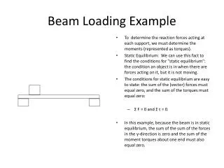
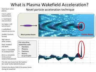
Transformer Ratio • Beam loading can occur because of a trailing beam or captured background electrons
Required Charge for Beam Loading Our beam’s Characteristics np=2.7x10¹⁷,N=1.3x10¹⁰,σr=3 μm, σz=35 μm • nb>np • Pencil beam • Long beam • Λ~1 Q>110 pC Src: M. Tzoufras, PRL (2008)
Betatron Oscillations in Plasma • X-ray yield depends on the number of oscillations • If the trapped charge is a function of interaction length, we are prominently trapping Rb II. Evolution of beam envelope Rb Dark Current Region Ar Ar RbII ArII RbI Ar RbII/ArII ArI RbII
Absolute Calibration of Length Length is absolutely calibrated using experimental results from two ovens
Raw Data and Transformer Ratio Transformer ratio reduces with excess charge No Foil Foil3 Foil2 Foil1 x2 ÷6
Simulations Show Beam Loading • Simulation parameters: 2.7x10¹⁷, εN=250 mm-mrad • Simulations where Rb II or Ar are turned off, showed little to no beam loading.
Reduction in Transformer Ratio • E- drops because of head erosion • E+ drops at a faster rate than the E- because of beam loading
Conclusions • Distributed injection of electrons occurs due to beam induced ionization of Rb+ • These electrons can beam load the wake and reduce the accelerating field. • Quantified this effect by correlating the increase of Rb II electrons with energy gain and loss of the different slices of the drive electron bunch as the plasma length is varied. • PIC simulations shows that this correlation is indeed the cause of the reduction of the transformer ratio due to the beam loading effect.
Future Work • This has given rise to mixed gas experiment to produce decent quality and high energy beam • Will write a long paper once this is accepted.
Data Corroboration for the Two Ovens • Trapped charge has the same form as X-ray Yield
Dipole radiation on X-rays Schematically shown blocked radiation Actual blocked radiation