Download
1 / 10
100 likes | 200 Views
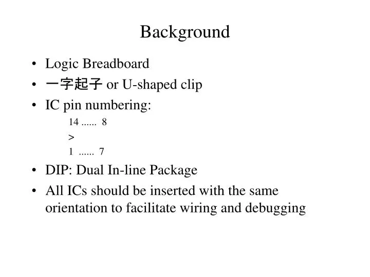
Background. Logic Breadboard 一字起子 or U-shaped clip IC pin numbering: 14 ...... 8 > 1 ...... 7 DIP: Dual In-line Package All ICs should be inserted with the same orientation to facilitate wiring and debugging. Wiring. Run all wires around ICs, not over them

E N D
Background • Logic Breadboard • 一字起子 or U-shaped clip • IC pin numbering: 14 ...... 8 > 1 ...... 7 • DIP: Dual In-line Package • All ICs should be inserted with the same orientation to facilitate wiring and debugging
Wiring • Run all wires around ICs, not over them • Easy debug and easy replace. • Try not to cover up too many unused holes with your wires • Keep wires close to the surface of the breadboard, and make them as short as possible subject to the preceding constraints. • RED: +5 volts; BLACK: Ground; YELLOW: +12 volts; WHITE: Negative voltage; VIOLET: Control; ORANGE: Data bus; BROWN: Address bus
Wiring Procedure • Wire the power. • Wire unused inputs: +5V through a 1K current-limiting resistor or ground. • Wire all regular buses. • Wire all control lines. • Check wiring of each IC sequentially. • Double-check all power connections before applying power
Damage • The one sure way to permanently damage an IC is to reverse power and ground. • Most of the time you will NOT damage an IC by shorting one of its outputs. • The totem-pole outputs can be shorted together or to ground without damage. • However, when an output trying to maintain a LOW level is shorted to the 5V supply there is usually damage.
Debugging • A small circuit will sometimes work properly the first time it is turned on • All other circuits require DEBUGGING • Use an ohmmeter to perform a continuity check. • After checking for SMOKE when the circuit is first powered, it is necessary to start debugging at a lower level • Two types of errors: wiring errors and design errors. • To work backwards in the circuit from some point that has a predictable behavior
Errors • The most common wiring errors are omitted and misplaced wires. • The most common design errors involve the disposition of unused inputs. • The next most common design errors involve the 1s and 0s catching behavior of master/slave J-K flip-flops.
Outputs • Open-collector outputs and wired logic • Three-state outputs
Operating Characteristics • VCC: Supply voltage • (4.75V, 5V, 5.25V) • VIH: high level input voltage • > 2V • VIL: low level input voltage • < 0.8V • VOH: high level output voltage • (2.5V, 3.4V, ) • VOL: low level output voltage • ( , 0.35V, 0.5V)
Operating Characteristics • IOH: high level output current • > -400 uA • IOL: low level output current • < 8 mA • IIH: high level input current • < 20 uA • IIL: low level input current • > -0.4 mA • ICC: supply current • ( , 6mA, 10 mA)
Propagation Delay • tpd: propagation delay • tPLH: low-to-high-level output • tPHL: high-to-low-level output • tPHZ: disable time from high level • tPLZ: disable time from low level • tPZH: enable time from high level • tPZL: enable time from low level