Download
1 / 36
380 likes | 430 Views
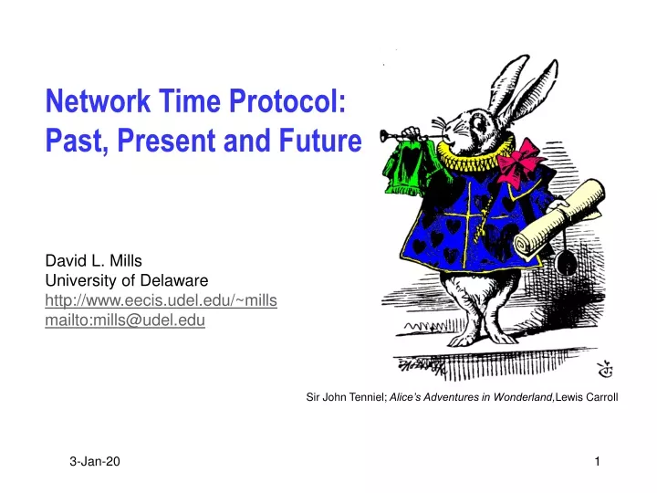
Network Time Protocol: Past, Present and Future. David L. Mills University of Delaware http://www.eecis.udel.edu/~mills mailto:mills@udel.edu. Overview. NTP architecture, protocol and algorithms Twenty years of analysis, modeling and refinement Splitting the microsecond

E N D
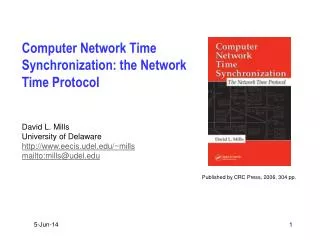
Network Time Protocol: Past, Present and Future David L. Mills University of Delaware http://www.eecis.udel.edu/~mills mailto:mills@udel.edu
Overview • NTP architecture, protocol and algorithms • Twenty years of analysis, modeling and refinement • Splitting the microsecond • We can do it with modern networks and computers • Modeling and performance analysis • Optimizing the parameters and kernel timekeeping code • Timekeeping in the Interplanetary Internet • And now for something completely different
Introduction • Network Time Protocol (NTP) synchronizes clocks of hosts and routers in the Internet • Probably several hundred thousand NTP servers and clients deployed in the Internet and its tributaries all over the world, including Antarctica • Provides nominal accuracies of low tens of milliseconds on WANs, submilliseconds on LANs, and submicroseconds using a precision time source such as a cesium oscillator or GPS receiver • Unix NTP daemon ported to almost every workstation and server platform available today - from PCs to Crays - Unix, Windows, VMS and embedded systems • NTP architecture, protocol and algorithms have been evolved over the last twenty years to the latest NTP Version 4
Evolution to NTP Version 4 • Current Network Time Protocol Version 3 has been in use since 1992, with nominal accuracy in the low milliseconds • Modern workstations and networks are much faster today, with attainable accuracy in the low microseconds and submicroseconds • NTP Version 4 architecture, protocol and algorithms have been evolved to achieve this degree of accuracy • Improved clock models which accurately predict the phase and frequency noise for each synchronization source and network path • Engineered algorithms which reduce the impact of network jitter and oscillator wander while speeding up initial convergence • Redesigned clock discipline algorithm which can operate in frequency-lock, phase-lock and hybrid modes • The improvements, confirmed by simulation, improve accuracy by about a factor of ten, while allowing operation at much longer poll intervals without significant reduction in accuracy
NTP autonomous system model • Fire-and-forget software • Single software distribution can be built and installed automatically on most host architectures and operating systems • Run-time configuration can be automatically determined and maintained in response to changing network topology and server availability • Autonomous configuration (autoconfigure) • Survey nearby network environment to construct a list of suitable servers • Select best servers from among the list using a defined metric • Reconfigure the NTP subnet for best accuracy with overhead constraints • Periodically refresh the list in order to adapt to changing topology • Autonomous authentication (autokey) • For each new server found, fetch and verify its cryptographic credentials from public databases • Authenticate each received NTP message with cryptographic message digest verified by digital signature • Regenerate keys in a timely manner to avoid compromise
NTP capsule summary • Primary (stratum 1) servers synchronize to national time standards via radio, satellite and modem • Secondary (stratum 2, ...) servers and clients synchronize to primary servers via hierarchical subnet • Clients and servers operate in client/server, symmetric or multicast modes with or without cryptographic authentication • Reliability assured by redundant servers and diverse network paths • Engineered algorithms reduce jitter, mitigate multiple sources and avoid improperly operating (Byzantine) servers • System clock is disciplined in time and frequency using an adaptive algorithm responsive to network time jitter and clock oscillator frequency wander
NTP architecture overview Peer 1 Filter 1 Selection and Clustering Algorithms Clock DisciplineAlgorithm • Multiple servers/peers provide redundancy and diversity • Clock filters select best from a window of eight time offset samples • Selection and clustering algorithms pick best truechimers and discard falsetickers • Combining algorithm computes weighted average of time offsets • Loop filter and variable frequency oscillator (VFO) implement hybrid phase/frequency-lock (P/F) feedback loop to minimize jitter and wander Combining Algorithm Peer 2 Filter 2 Loop Filter Peer 3 Filter 3 Timestamps VFO NTP Messages
NTP protocol header and timestamp formats NTP Protocol Header Format (32 bits) LI leap warning indicator VN version number (4) Strat stratum (0-15) Poll poll interval (log2) Prec precision (log2) LI VN Mode Strat Poll Prec Root Delay Root Dispersion Reference Identifier Reference Timestamp (64) NTP Timestamp Format (64 bits) Originate Timestamp (64) Seconds (32) Fraction (32) Value is in seconds and fraction since 0h 1 January 1900 Cryptosum Receive Timestamp (64) Transmit Timestamp (64) NTPv4 Extension Field Extension Field 1 (optional) Field Length Field Type Extension Field (padded to 32-bit boundary) Extension Field 2… (optional) Last field padded to 64-bit boundary Key/Algorithm Identifier NTP v3 and v4 Authenticator (Optional) Message Hash (64 or 128) NTP v4 only authentication only Authenticator uses DES-CBC or MD5 cryptosum of NTP header plus extension fields (NTPv4)
Clock filter algorithm T2 Server T3 • The most accurate offset q0 is measured at the lowest delay d0 (apex of the wedge scattergram). • The correct time q must lie within the wedge q0 ± (d - d0)/2. • The d0 is estimated as the minimum of the last eight delay measurements and (d0 ,q0) becomes the offset and delay output. • Each output can be used only once and must be more recent than the previous output. • The distance metric l is based on delay, frequency tolerance and time since the last measurement. x q0 T1 Client T4
Selection algorithm B • Marzullo correctness interval is the intersection which contains points from the largest number of correctness intervals • NTP algorithm requires the midpoint of the intervals to be in the intersection for minimum jitter • Initially, set falsetickers f and counters c and d to zero • Scan from far left endpoint: add one to c for every lower endpoint, subtract one for every upper endpoint, add one to d for every midpoint • If c³ m-f and d³ m-f, declare success and exit procedure • Do the same starting from the far right endpoint • If success undeclared, increase f by one and try all over again • if fm/2, declare failure correctness interval = q - l £ q0 £ q + l m = number of clocks f = number of presumed falsetickers A, B, C are truechimers D is falseticker A D C Correct Marzullo Correct NTP
Clustering algorithm Sort survivors of intersection algortihm by increasing synchronization distance. Let n be the number of survivors and nmin a lower limit. For each survivor si, compute the select dispersion (weighted sum of clock difference squares) between si and all others. Let smax be the survivor with maximum select dispersion (relative to all other survivors) and smin the survivor with minimum sample dispersion (clock differences relative to past samples of the same survivor). smax£smin or n£ nmin? yes no Delete the survivor smax; reduce n by one The resulting survivors are processed by the combining algorithm to produce a weighted average used as the final offset adjustment
Error budget Sample Variables Peer Variables System Variables S S Peer A S Peer B NTP Version 4 Error Budget
Kernel modifications for nanosecond resolution • Package of routines compiled with the operating system kernel • Represents time in nanoseconds and fraction, frequency in nanoseconds per second and fraction • Implements nanosecond system clock variable with either microsecond or nanosecond kernel native time variables • Uses native 64-bit arithmetic for 64-bit architectures, double-precision 32-bit macro package for 32-bit architectures • Includes two new system calls ntp_gettime() and ntp_adjtime() • Includes new system clock read routine with nanosecond interpolation using process cycle counter (PCC) • Supports run-time tick specification and mode control • Guaranteed monotonic for single and multiple CPU systems
Improved NTP clock discipline qr+ Vd Vs • Type II, adaptive-parameter, hybrid phase/frequency-lock loop disciplines variable frequency oscillator (VFO) phase and frequency • NTP daemon computes phase error Vd= qr- qo between source and VFO, then grooms samples to produce time update Vs • Loop filter computes phase x and frequency y corrections and provides new adjustments Vc at 1-s intervals • VFO frequency adjusted at each hardware tick interrupt NTP Daemon NTP Phase Detector Clock Filter qc- VFO Kernel Loop Filter x Vc ClockAdjust Phase/FreqPrediction y
FLL/PLL prediction functions PhaseCorrect x yFLL FLLPredict Vs S y yPLL PLLPredict • Vs is the phase offset produced by the clock filter algorithm • x is the phase correction computed as a fraction of Vs • yFLL is the frequency adjustment computed as the average of past frequency offsets • yPLL is the frequency adjustment computed as the integral of past phase offsets • yFLL and yPLL are combined according to weight factors determined by poll interval and Allan deviation characteristic
Nanokernel architecture Phase Prediction PLL/FLL Discipline NTP Update ClockOscillator CalculateAdjustment Frequency Prediction PPSDiscipline PPS Interrupt TickInterrupt SecondOverflow • PLL/FLL discipline predicts phase x and frequency y at averaging intervals from 1 s to over one day • PPS discipline predicts phase and frequency at averaging intervals from 4 s to 128 s, depending on nominal Allan intercept • On overflow of the clock second, a new value is calculated for the tick adjustment • Tick adjustment is added to system clock at every tick interrupt • Process cycle counter (PCC) used to interpolate microseconds or nanoseconds between tick interrupts
Improved PPS phase and frequency discipline SecondOffset MedianFilter RangeChecks Phase Average x PPSInterrupt FrequencyDiscrim PCCCounter AmbiguityResolve Range Checks Frequency Average y • Phase and frequency disciplined separately - phase from system clock offset relative to second, frequency from process cycle counter (PCC) • Frequency discriminator rejects noise and incorrect frequency sources • Median filter rejects sample outlyers and provides error statistic • Range checks reject popcorn spikes in phase and frequency • Phase offsets exponentially averaged with variable time constant • Frequency offsets averaged over variable interval
Phase and frequency noise characterization Phase noise is Gaussian process with parameter r • Parameter r is determined primarily by network and system jitter • Characteristic on log-log coordinates is a straight line with slope -1 • Synthetic phase noise can be generated by Gaussian process with parameter r • Frequency noise is random-walk Gaussian process with parameter s • Parameter s is determined primarily by oscillator frequency wander • Characteristic on log–log coordinates is a straight line with slope +0.5 • Synthetic frequency noise can be generated by twice-integrating Gaussian process with parameter s • Allan intercept is determined by the intersection of the phase and frequency characteristics • The intercept for each architecture is useful to determine the optimum averaging method and time constant
Allan deviations compared SPARC IPC Pentium 200 Alpha 433 Resolution limit
Experimental results with PPS discipline • Hepzibah is a 400-MHz Pentium workstation with a GPS receiver • The PPS signal is connected via parallel port and modified driver • Rackety is a 25-MHz SPARC IPC dedicated NTP server with dual redundant GPS receivers and dual redundant WWVB receivers • This machine has over 1000 clients causing a load of 15 packets/sec • The PPS signal is connected via serial port and modified driver • Churchy is a 433-MHz Alpha workstation with a GPS receiver • This machine uses a SAW oscillator presumed spectrally pure • The PPS signal is connected via serial port and modified driver • All machines accessed the PPS signal from a GPS receiver and a level converter where necessary • Experiments lasted one day with data collected by the NTP daemon
PPS time offset characteristic for Hepzibah • Jitter is presumed caused by interrupt latencies on the ISA bus • We need to explain why the spikes are both positive and negative
PPS time offset characteristic for Rackety • Jitter is presumed caused by interrupt latencies on the Sbus • Large negative spikes reflect contention by the radios and network
PPS time offset characteristic for Churchy • Jitter is presumed caused by interrupt latencies on the PCI bus • High flicker noise may be due to SAW phase noise and no PLL
The Sun never sets on NTP • NTP is arguably the longest running, continuously operating, ubiquitously available protocol in the Internet • USNO and NIST, as well as equivalents in other countries, provide multiple NTP primary servers directly synchronized to national standard cesium clock ensembles and GPS • Over 230 Internet primary servers in Australia, Canada, Chile, France, Germany, Israel, Italy, Holland, Japan, Norway, Spain, Sweden, Switzerland, UK, and US - the list goes on • Over 100,000 Internet secondary servers and clients all over the world • National and regional service providers BBN, MCI, Sprint, Alternet, etc. • Agencies and organizations: US Weather Service, US Treasury Service, IRS, PBS, Merrill Lynch, Citicorp, GTE, Sun, DEC, HP, etc. • Several private networks are reported to have over 10,000 NTP servers and clients; one (GTE) reports in the order of 30,000 NTP-equipped workstations and PCs
UDel Master Time Facility (MTF) Spectracom 8170 WWVB Receiver Spectracom 8183 GPS Receiver Spectracom 8170 WWVB Receiver Spectracom 8183 GPS Receiver Hewlett Packard 105A QuartzFrequency Standard Hewlett Packard 5061A Cesium BeamFrequency Standard NTP primary time servers rackety and pogo (elsewhere)
Gadget Box PPS interface • Used to interface PPS signals from GPS receiver or cesium oscillator • Pulse generator and level converter from rising or falling PPS signal edge • Simulates serial port character or stimulates modem control lead • Also used to demodulate timecode broadcast by CHU Canada • Narrowband filter, 300-baud modem and level converter • The NTP software includes an audio driver that does the same thing
LORAN-C timing receiver • Inexpensive second-generation bus peripheral for IBM 386-class PC with oven-stabilized external master clock oscillator • Includes 100-kHz analog receiver with D/A and A/D converters • Functions as precision oscillator with frequency disciplined to selected LORAN-C chain within 200 ns of UTC(LORAN) and 10-10 stability • PC control program (in portable C) simultaneously tracks up to six stations from the same LORAN-C chain • Intended to be used with NTP to resolve inherent LORAN-C timing ambiguity
Interplanetary Internet (IPIN) • Research program funded by DARPA and NASA • Near term emphasis on Mars exploration and mission support • Exploration vehicles • Surface base stations and rovers – perform experiments, collect data • Satellite orbiters – relay commands to surface vehicles, retrieve data for later transmission to Earth • Spacecraft – transport orbiters and surface vehicles to Mars • Mission support • NASA Deep Space Network (DSN) – three huge antenna farms in California, Spain and Australia, time shared for Mars and other NASA missions • Earth internet – coordinate mission activities, send commands and retrieve data via DSN, disseminate results • MARS internet – communicate between DSN, orbiters and surface vehicles; perform housekeeping functions such as antenna pointing, network routing, ephemeris maintenance and general timekeeping
IPIN timekeeping issues • Transmission delays between Earth and Mars are variable and in general much longer than in Earth and Mars internets • Transmission speeds are highly variable, but in general far slower than Earth internet • Spacecraft position and velocity can be predicted accurately, so transmission delays can be predicted • Connectivity between Mars surface and orbiters and between Earth and Mars is not continuous, but opportunities can be predicted • DSN facilities are shared; connectivity opportunities must be scheduled in advance for each mission • Error recovery using retransmissions is impractical; TCP is useful only in Earth internet and Mars internet, but not between Earth and Mars • Dependency on Earth-based databases is not practical on Mars, so any databases required must be on or near Mars
NTP online resources • Network Time Protocol (NTP) Version 3 Specification RFC-1305 • NTPv4 features documented in release notes and reports cited there • Simple NTP (SNTP) Version 3 specification RFC-2030 • Applicable to IPv4, IPv6 and ISO CNLS • List of public NTP time servers (as of May 2001) • 107 active primary (stratum 1) servers • 136 active stratum 2 servers • NTP Version 4 implementation and documentation for Unix, VMS and Windows • Ported to over two dozen architectures and operating systems • Utility programs for remote monitoring, control and performance evaluation • Complete documentation in HTML format • Collaboration resources at http://www.eecis.udel.edu/~mills/resource.htm
Further information • Network Time Protocol (NTP): http://www.ntp.org/ • Current NTP Version 3 and 4 software and documentation • FAQ and links to other sources and interesting places • David L. Mills: http://www.eecis.udel.edu/~mills • Papers, reports and memoranda in PostScript and PDF formats • Briefings in HTML, PostScript, PowerPoint and PDF formats • Collaboration resources hardware, software and documentation • Songs, photo galleries and after-dinner speech scripts • FTP server ftp.udel.edu (pub/ntp directory) • Current NTP Version 3 and 4 software and documentation repository • Collaboration resources repository • Related project descriptions and briefings • See “Current Research Project Descriptions and Briefings” at http://www.eecis.udel.edu/~mills/status.htm